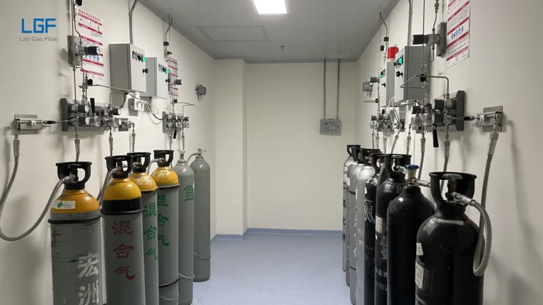

A UHP gas manifold configuration is the complete arrangement that connects one or more gas cylinders to a controlled outlet while preserving gas purity, stable pressure, safe cylinder changeover and maintainable isolation. The correct configuration is not defined by the number of valves on a panel. It is defined by the gas hazard, required purity at the instrument, peak and normal flow, acceptable pressure variation, required supply continuity, cylinder-change procedure and future expansion plan.
For most analytical laboratories, a practical configuration starts with gas-specific cylinder connections, stainless-steel pigtails, individual cylinder isolation, non-return protection, one or two pressure-reduction stages, an inert-gas purge path, a controlled vent, outlet isolation and pressure indication. A duty/standby arrangement adds a second cylinder bank and a changeover mechanism. Hazardous or highly reactive gases may also require an exhausted enclosure, gas detection, automatic shutdown and facility interlocks. Each feature should solve an identified operating or safety requirement; adding components without a defined purpose increases internal volume, leak paths and maintenance burden.
What Does “UHP” Mean in a Gas Manifold?
Ultra-high-purity service means the manifold must avoid adding measurable moisture, oxygen, hydrocarbons, particles or incompatible residues to the gas stream. A cylinder labeled with a high gas grade does not guarantee that the instrument receives the same quality. Gas quality can be degraded by permeation through unsuitable hoses, regulator outgassing, trapped atmospheric air, dirty assembly, excessive fittings, incomplete purging or a small leak that draws contaminants into the system.
A UHP manifold therefore controls both pressure and contamination. Typical design choices include 316L stainless-steel wetted components, packless diaphragm valves, low-internal-volume regulators, stainless-steel pigtails, face-seal or welded connections, compatible soft goods, clean assembly and documented leak testing. The exact specification should follow the allowable impurity budget and gas chemistry rather than a generic “UHP-ready” label.
UHP requirements are application-specific. A carrier gas for trace chromatography may be especially sensitive to oxygen, moisture and hydrocarbons, while a reactive process gas may place greater emphasis on compatible materials, safe purging and containment. The buyer should state gas composition, cylinder pressure, required outlet purity, allowable contaminants and analytical sensitivity before selecting components.
Source Manifold, Distribution Manifold and Point-of-Use Panel
A source manifold combines gas from one or more cylinders into a common controlled supply line. A distribution manifold divides that supply into several downstream branches. A point-of-use panel provides final isolation or pressure control near an instrument. These functions can share an enclosure in a small system, but they should remain distinct in the design documentation because they operate at different pressures and create different failure consequences.
A source manifold commonly contains the highest-pressure components in the laboratory gas delivery system. It must manage cylinder replacement, pressure reduction and, when required, automatic changeover. A distribution manifold usually operates at a lower header pressure and should allow one branch to be isolated without unnecessarily interrupting other instruments. A point-of-use regulator can provide more stable final pressure when the central header serves instruments with different requirements or when long piping runs create pressure losses.
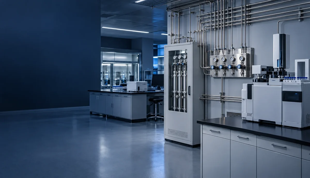
Projects often become difficult when “manifold” is used to describe all three functions. A quotation may include a cylinder changeover panel but omit branch isolation, or it may include multiple outlet valves without final pressure control. A functional block diagram should show the cylinder source, changeover boundary, pressure stages, purifier location, main header, branch valves, point-of-use controls and every purge or vent connection.
Which Basic Configuration Fits the Application?
| Configuration | Best fit | Main advantage | Main limitation |
|---|---|---|---|
| Single cylinder, single outlet | Intermittent work or noncritical instruments | Lowest internal volume and simplest operation | Supply stops during cylinder replacement |
| Single bank with several cylinders | Higher flow or longer runtime without automatic changeover | More available capacity | All connected cylinders share one service state |
| Manual duty/standby | Moderate continuity needs with trained operators present | Simple redundancy at moderate cost | Changeover depends on operator response |
| Automatic duty/standby | Unattended or continuity-critical instruments | Maintains supply when the duty bank is depleted | More controls, valves and validation work |
| Central header with branch manifold | Several instruments using the same compatible gas grade | Reduces cylinders in occupied laboratory areas | A common header can create a shared failure point |
| Dedicated manifold per instrument | Very sensitive, incompatible or independently qualified processes | Strong separation and clear ownership | More equipment, floor space and cylinder inventory |
A single-cylinder configuration is appropriate only when planned interruption is acceptable. If an instrument must remain supplied during cylinder replacement, the system needs a duty/standby source or another validated reserve. A larger single bank increases runtime but does not create true continuity because the entire bank eventually becomes unavailable for replacement or maintenance.
An automatic changeover manifold should switch sources before the outlet pressure falls below the process requirement. However, changeover alone does not guarantee stable instrument pressure. If the bank regulators operate at different set pressures to create the switching sequence, a final line regulator is often needed to reduce the changeover pressure step before gas enters the distribution header.
How Should the Pressure-Reduction Stages Be Arranged?
The pressure architecture should begin at the instrument, not at the cylinder. First record the minimum and maximum pressure each instrument accepts, its normal flow, peak flow and allowable pressure variation. Then calculate the pressure needed at the main header after allowing for pipe friction, filters, purifiers, valves, elevation and future branches. The manifold outlet setpoint must be high enough to serve the most demanding operating case but below the working limit of every downstream component.
A single pressure-reduction stage is compact and can be suitable when cylinder-pressure decay does not disturb the process. A two-stage arrangement reduces pressure in two controlled steps and generally provides better outlet stability across the cylinder cycle. Two separate regulators can also divide source control from final header control, making the system easier to diagnose and maintain.
Regulator capacity must be evaluated at the actual inlet and outlet conditions. A nominal port size does not prove adequate flow. The procurement specification should state the gas, maximum inlet pressure, minimum inlet pressure at changeover, desired outlet pressure, normal flow, coincident peak flow and permitted droop. For a deeper comparison of regulation behavior, see the guide to single-stage and two-stage laboratory gas regulators.
Relief protection must be matched to the downstream pressure rating and directed to an appropriate discharge location. A trapped section of piping can also need pressure protection when temperature rise or regulator leakage could increase pressure. Relief devices are safety components, not routine pressure controls, and their setpoints should not be used to compensate for an incorrectly selected regulator.
How Are Cylinder Banks and Changeover Logic Configured?
A duty/standby manifold has two source sides feeding a common outlet. The duty bank supplies gas until its pressure reaches the changeover threshold, after which the standby bank becomes the active source. A manual system requires an operator to move valves or a selector. A semi-automatic system changes banks through a pressure relationship but requires the operator to reset the full side. A fully automatic system can use sensors, pneumatic valves or electronic logic to manage switching, alarms and permissives.
The changeover threshold must leave enough residual pressure for stable control and must account for peak demand. Setting the threshold too low can create outlet-pressure decay before the reserve bank takes over. Setting it unnecessarily high leaves usable gas in the depleted cylinder and increases operating cost. The correct setting is derived from regulator behavior, flow demand and the acceptable line-pressure disturbance.
Each cylinder connection should be independently isolatable. A non-return device helps prevent gas from a full bank from feeding into an empty or disconnected side, but it should not replace a positive isolation valve. The arrangement should let technicians replace one bank while the other remains in service without opening the active gas path to atmosphere.
What Is the Correct Purge and Vent Topology?
A purge system must displace air from every volume that can be exposed during cylinder replacement or maintenance. The most useful design question is not “Does the panel have a purge valve?” but “Which trapped volumes are swept, in what direction, and where does the displaced gas go?” Pigtails, regulator cavities, valve branches and dead-ended gauge connections can retain air even when the main header has been purged.
A common cylinder-change sequence isolates the process, depressurizes the replaceable section to a controlled vent, introduces clean inert purge gas, repeats purge and evacuation or pressure cycling as specified, and then introduces process gas without exposing the downstream header. The number of cycles and acceptance criterion should be based on system volume, gas properties and required purity rather than a universal number.
Purge gas must not create a backflow route into the process cylinder or another gas service. Check valves, positive isolation and pressure relationships should be considered together. The vent path must be compatible with the gas and must terminate where a release can be handled safely. Toxic, corrosive, pyrophoric or flammable gases require a project-specific review of exhaust, treatment, detection and emergency response.
The U.S. Occupational Safety and Health Administration notes that compressed gases may present pressure, toxicity, fire, explosion and oxygen-displacement hazards. Facility design and operating procedures should therefore be based on the actual gas inventory and applicable local requirements, not only on purity goals. The site’s laboratory gas hardware compliance guide explains how cylinders, manifolds, piping, shutoffs, vents and detection fit into a broader safety review.
Which Wetted Materials and Connections Preserve UHP Gas?
316L stainless steel is widely specified for UHP gas paths because it combines corrosion resistance, cleanability and compatibility with welded or metal-sealed construction. Material grade alone is insufficient. Surface finish, cleaning, passivation or electropolishing requirements, assembly environment, packaging and handling all influence the final contamination level.
Packless diaphragm valves are generally preferred over packed valves because the diaphragm separates the operating mechanism from the gas path and reduces atmospheric ingress. Regulators should use compatible diaphragms, seats and seals with low outgassing and low internal volume. Pigtails for helium, hydrogen and demanding UHP service are commonly specified with stainless-steel inner construction because polymer-lined hoses can introduce permeation or diffusion concerns.
Every mechanical connection adds a potential leak and trapped volume. Welded tubing reduces connection count in permanent sections, while demountable metal face-seal fittings are useful where a component must be replaced. Compression fittings may be appropriate in some laboratory systems, but the owner should define where they are allowed and how they will be inspected. The article on laboratory gas piping and fitting selection provides additional procurement criteria.
How Should a Multi-Outlet Distribution Manifold Be Designed?
A multi-outlet manifold should allow each instrument branch to be identified, isolated and serviced without contaminating adjacent branches. The main header is sized for credible simultaneous demand, not simply the sum of every nameplate maximum or the average flow. A diversity assumption is acceptable only when the operating schedule proves that certain loads cannot occur together.
Branch pressure control can be centralized or located at the point of use. Central regulation is simpler when all instruments need similar pressure and the piping runs are short. Point-of-use regulation is more flexible when instruments require different pressures, when branch lengths vary, or when the process needs a stable final pressure close to the consumer. A hybrid arrangement uses a moderate-pressure header with individual final regulators.
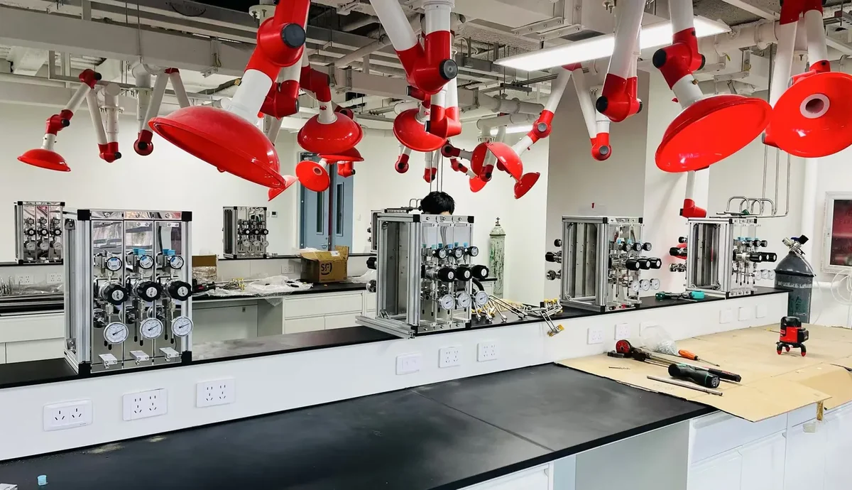
Unused future branches should be designed intentionally. A capped stub can become a contamination trap and an unidentified dead leg. A better expansion plan defines the valve, cap or welded closure, purge method, labeling and commissioning procedure required before the spare branch is placed in service.
Where Should Purifiers, Filters and Instruments Be Located?
A purifier should be selected for the gas and contaminants of concern, with capacity, pressure drop, flow range and replacement method documented. Installing a purifier at the source protects all downstream users but creates a common maintenance point. Installing purification at the point of use protects a sensitive instrument from contaminants introduced along the header but adds components and connections near the instrument. Critical systems may use both approaches for different impurity targets.
Filters protect sensitive components from particles, but a filter does not remove moisture or oxygen unless it is specifically designed as a purifier. Filter pore rating, housing cleanliness, pressure drop and installation orientation should be specified. Placing a filter without a replacement isolation plan can force shutdown of the entire system.
Pressure gauges provide local indication, while pressure transmitters support remote alarms and trend analysis. Sensors should be located where the reading answers an operational question: cylinder availability, changeover performance, header stability or point-of-use pressure. Instrument branches should minimize stagnant volume and use compatible isolation so a failed sensor can be replaced without exposing the full UHP system.
What Controls and Interlocks Are Appropriate?
Control complexity should follow risk and uptime requirements. A manual inert-gas manifold serving a supervised instrument may need only clear valve identification and pressure indication. An unattended automatic system may need bank-low alarms, changeover status, high- and low-outlet-pressure alarms, purge permissives, emergency shutdown inputs and communication with the building management or laboratory monitoring system.
The fail-safe state must be defined for loss of electrical power, instrument air, exhaust or communication. Closing process-gas valves on loss of power is common for hazardous services, but the complete response must consider trapped gas, purge availability and instrument consequences. Safety shutdown should not depend only on a software screen; the architecture should identify which functions are hardwired, which are programmable and how they are tested.
Alarm messages should tell operators what condition occurred and what action is required. A generic “gas fault” alarm is less useful than separate indications for duty-bank low pressure, failed changeover, high outlet pressure, purge pressure unavailable and enclosure exhaust failure. Alarm setpoints, delays and reset behavior belong in the functional specification.
How Do Gas Properties Change the Configuration?
Inert gases still require pressure control, cylinder restraint and oxygen-deficiency assessment where a release could displace air. Flammable gases require ignition-control, ventilation, leak detection and emergency isolation decisions appropriate to the inventory and room. Oxidizing gases require oxygen-compatible materials and cleanliness. Corrosive or toxic gases require careful compatibility, containment, purging, vent treatment and maintenance planning.
Gas purity and gas hazard are separate design axes. A high-purity inert gas may need stringent contamination control but comparatively simple containment. A hazardous gas may need an exhausted cabinet and extensive interlocks even when the analytical purity requirement is modest. The manifold specification should contain both a purity classification and a hazard classification so neither requirement is lost.
Different gases should not share a common cylinder manifold. Even if two gases are used by the same instrument, independent source paths prevent accidental mixing and allow gas-specific connections, materials, purge procedures and labeling. Stream selection should occur in a purpose-designed downstream assembly only when the analytical method requires it and cross-contamination has been addressed.
How Should the Configuration Be Tested and Accepted?
Factory acceptance testing should confirm that the manufactured panel matches the approved drawings and functional description. Typical checks include component identity, valve orientation, tubing and weld inspection, pressure testing, helium leak testing to an agreed criterion, regulator operation, changeover behavior, alarm simulation, purge sequence, labeling and document completeness. The acceptance criterion should be written before fabrication, not negotiated after delivery.
Site acceptance testing should verify the installed system as a whole. It should include cylinder connections, supports, exhaust and vent routing, utility connections, interlocks, communications, downstream piping integrity, branch identification, pressure stability at representative demand and the complete cylinder-change procedure. A clean factory-tested panel can still be compromised by poor field tubing or uncontrolled installation.
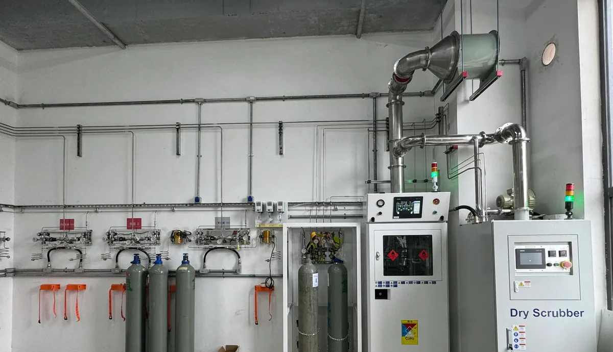
Purity acceptance may use moisture, oxygen, hydrocarbon, particle or application-specific measurements. The test location, instrument detection limit, sampling method, stabilization time and pass criterion should be defined. A leak-tight result does not by itself prove that the system is clean, and a clean initial sample does not replace a documented maintenance and cylinder-change procedure.
What Information Belongs in a UHP Manifold RFQ?
A useful request for quotation describes the operating requirement rather than asking only for “one UHP manifold.” Suppliers need enough information to size the system and identify safety boundaries. The RFQ should include:
- Gas name, composition, grade, cylinder connection and maximum cylinder pressure.
- Hazard classification, safety data sheet and applicable site or local requirements.
- Number of cylinders per bank and manual, semi-automatic or automatic changeover preference.
- Required outlet pressure, allowable variation, normal flow and coincident peak flow.
- Number of outlets, branch pressures, piping lengths and future expansion allowance.
- Required wetted materials, surface finish, valve type, connection type and soft-good restrictions.
- Purge gas source, purge method, vent destination and enclosure or exhaust requirements.
- Purifier, filter, gauge, transmitter, alarm, communication and emergency shutdown requirements.
- Leak-rate criterion, cleanliness or purity acceptance test, FAT and SAT scope.
- Required drawings, material certificates, weld records, test reports, manuals and spare-parts list.
The RFQ should also state the project boundary. Clarify who supplies cylinders, pigtails, source panel, main piping, point-of-use controls, exhaust, detection, electrical power, controls integration, installation and commissioning. Clear boundaries prevent a technically complete manifold from arriving without the utilities or downstream equipment required for operation.
Common Configuration Mistakes
The first common mistake is selecting a manifold from a catalog picture before creating a gas schedule. A visually similar panel may have the wrong regulator range, materials, flow capacity or purge arrangement. The second mistake is treating every additional valve as an improvement. Extra components can increase dead volume, surface area and leak opportunities.
The third mistake is specifying automatic changeover without defining outlet-pressure stability. The gas supply may switch successfully while the instrument still sees an unacceptable pressure step. The fourth mistake is adding a purge inlet without mapping the swept volume and vent destination. A purge connection that bypasses trapped sections creates a false sense of cleanliness.
The fifth mistake is designing only for normal operation. Cylinder change, sensor replacement, purifier replacement, branch expansion and emergency shutdown should be reviewed as separate operating states. A configuration is maintainable only when each service task has a safe isolation and recovery method.
A Practical Configuration Decision Sequence
- Define the process need. Record gas purity, pressure, normal flow, peak flow, allowable interruption and instrument sensitivity.
- Classify the gas. Separate purity requirements from toxicity, flammability, oxidizing, corrosive and asphyxiation hazards.
- Select the source arrangement. Choose single cylinder, multi-cylinder bank or duty/standby banks based on capacity and continuity.
- Build the pressure budget. Work backward from each instrument through point-of-use controls, branches, the header and the source regulators.
- Draw every flow path. Show process gas, purge gas, vent, relief, exhaust and future branches.
- Control contamination. Specify wetted materials, connections, dead-volume limits, cleaning, assembly and packaging.
- Define abnormal states. Document responses to empty cylinders, leaks, high pressure, loss of power, loss of exhaust and maintenance isolation.
- Write acceptance criteria. Agree on inspection, leak testing, functional tests, purity verification and documentation before fabrication.
This sequence complements the broader laboratory gas manifold selection guide and the system-level workflow for choosing a laboratory gas delivery system. The configuration article focuses specifically on how the functional requirements become a manifold topology and an auditable procurement specification.
Final Selection Guidance
The best UHP gas manifold configuration is the simplest arrangement that can meet purity, pressure, flow, continuity, safety and maintenance requirements under both normal and abnormal conditions. A single-cylinder panel may be correct for an intermittent instrument, while a dual-bank automatic changeover system may be essential for unattended analysis. A central distribution header can reduce cylinder handling, but dedicated lines may be justified for incompatible gases or exceptionally sensitive measurements.
LGF Lab Gas Flow supports B2B laboratory owners, engineering contractors, system integrators and equipment manufacturers with configurable gas manifolds, source panels, point-of-use controls and complete laboratory gas delivery systems. For a project review, prepare the gas schedule, pressure and flow requirements, required uptime, room layout and applicable safety requirements. Visit LGF Lab Gas Flow to review additional system information and discuss a custom UHP gas manifold configuration for your laboratory or production facility.