
LGF LAB GAS FLOW / PROJECT CASES
University Laboratory Specialty Gas Upgrade
An existing university laboratory rarely offers an empty, unrestricted route for new gas services. This illustrated case examines how a specialty-gas upgrade can be planned around active rooms, changing instruments and the limits of an existing building.
AN ILLUSTRATED PROJECT REVIEW
How this laboratory gas project takes shape
The practical starting point is a room-by-room instrument survey. A change to one research group may affect a shared source, a corridor route and neighboring users. Before selecting a manifold or a new branch, the team should record each instrument’s gas identity, grade, inlet pressure, peak and normal flow, operating pattern and expected future position. The same gas name does not automatically mean two instruments can share the same delivery path: contamination sensitivity, permitted pressure variation and the consequences of interruption can differ.
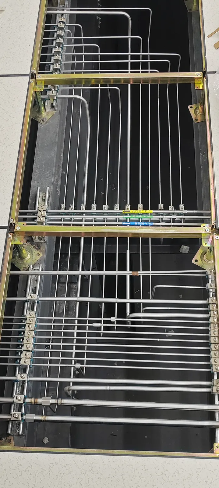
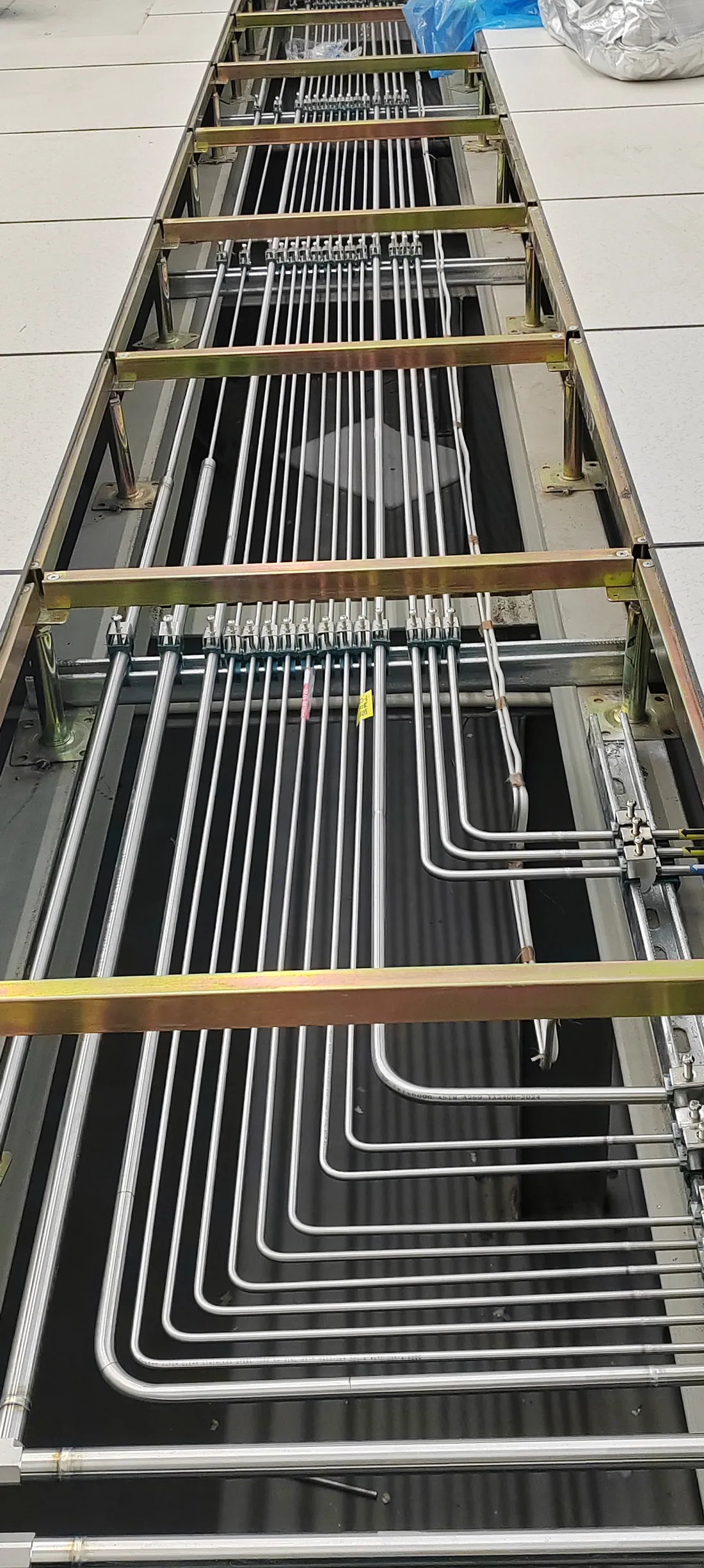
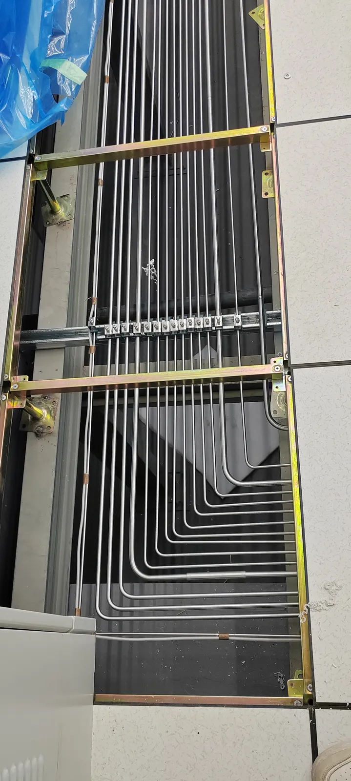
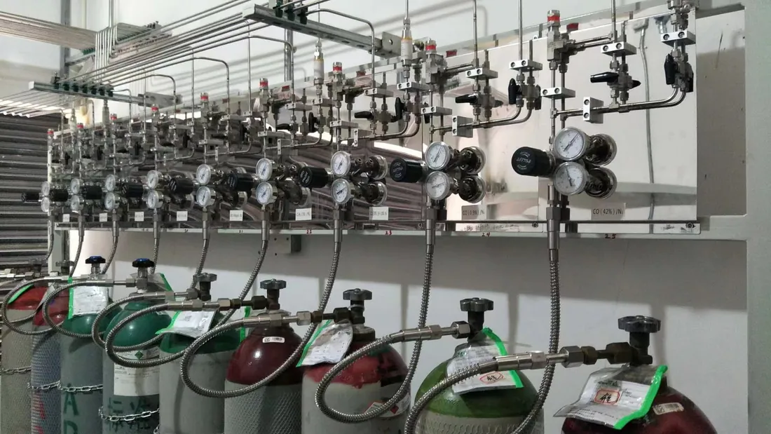
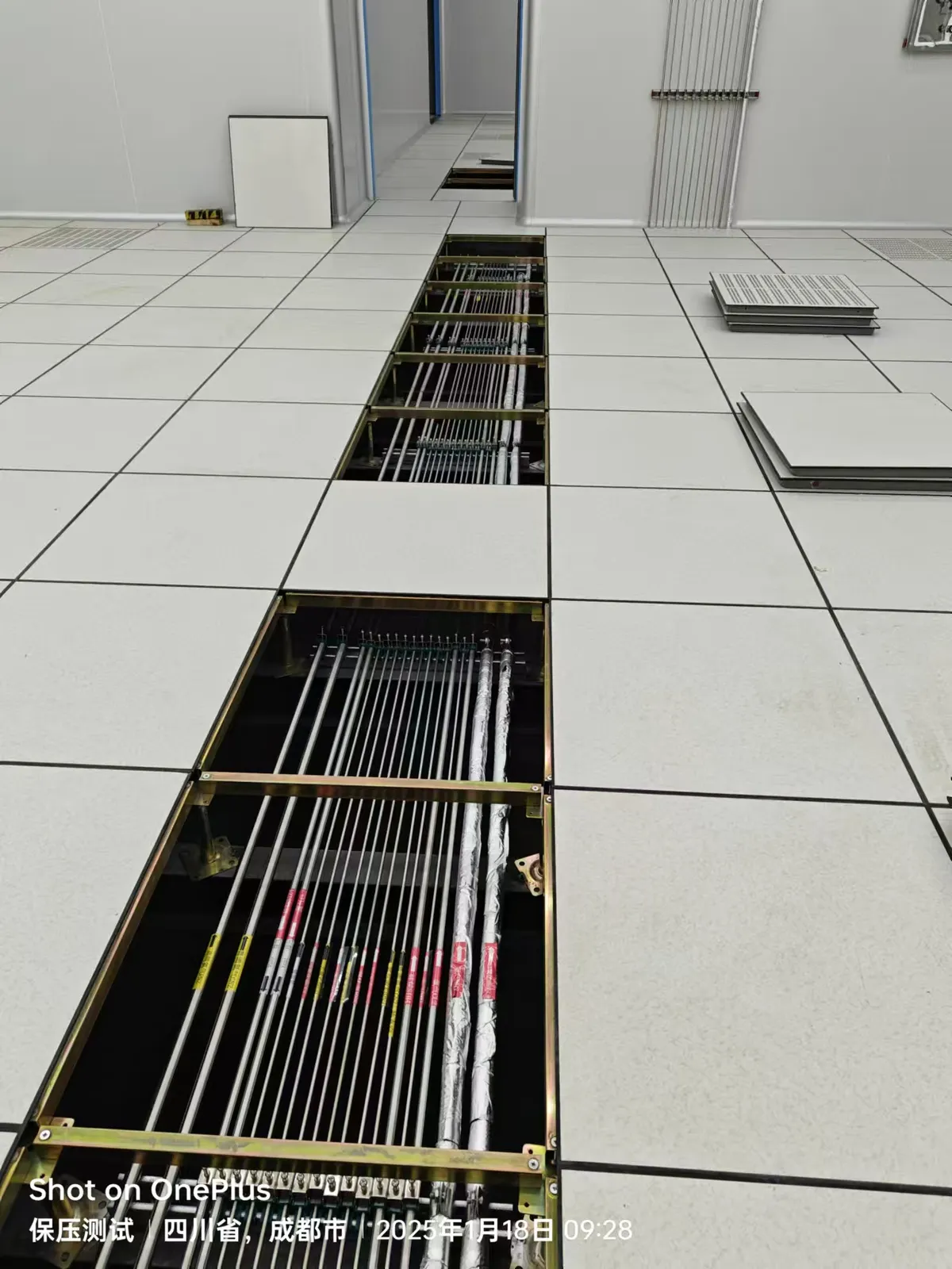
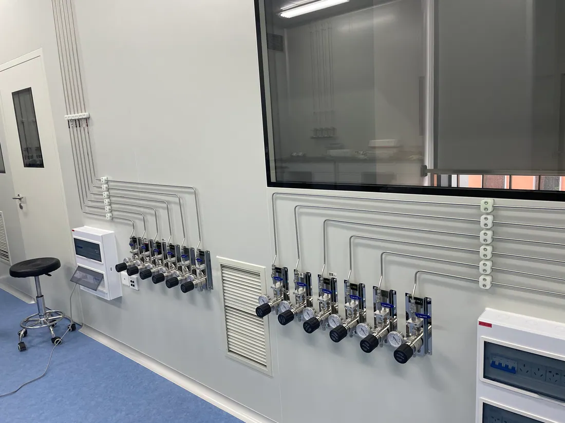
The project photographs show routing, terminal and support details typical of a laboratory gas piping renovation. They establish visible physical arrangements, not the exact gases, purity grades, acceptance results or customer identity of a finished installation. The engineering narrative below therefore focuses on decisions a university project team can verify and document.
01 / EXISTING CONDITIONS
Survey the building before drawing a new gas route
Existing rooms contain ceiling services, structural penetrations, fire boundaries and equipment that may have been altered several times. A survey should locate available source areas, risers, accessible ceiling zones, isolation valves and outlet positions. The team must determine which existing lines are in service, what each line actually carries and whether any component can be reused under the new operating brief. Labels and old drawings are useful leads, but field verification matters.
A route that looks short on a plan may cross an inaccessible ceiling or disrupt a teaching room. For occupied laboratories, the sequence of isolating an old service, installing new pipework, testing and reconnecting instruments may matter more than a small reduction in pipe length. A phased drawing should show temporary boundaries and who authorizes each shutdown.
02 / GAS AND SOURCE MATRIX
Separate shared utilities from sensitive specialty gases
A university research laboratory may use nitrogen, argon or other routine utilities alongside dedicated high-purity or hazardous gases. The gas-by-gas matrix should distinguish source grade, cylinder connection, regulator range, required outlet pressure, simultaneous demand and instrument sensitivity. Shared distribution can simplify cylinder management when users have compatible requirements. A dedicated line is more appropriate when a common route would compromise cleanliness, control or safe operation.
Source location is not only a distance calculation. Cylinder exchange access, cabinet or manifold arrangement, ventilation, detection, purge interfaces and emergency response must be reviewed with the facility team for the actual gas hazards. The university’s safety and engineering owners should approve the source concept before the laboratory gas delivery system is detailed.
03 / DISTRIBUTION ROUTE
Make each line identifiable and maintainable
The photographs of vertical and horizontal pipe runs show why a clear route schedule helps installers and future maintenance teams. A 316L stainless steel laboratory gas line may be specified for many high-purity services, but the final material, surface finish, connection style and cleaning method depend on the gas and target quality at the point of use. Support design must account for access, mechanical protection and neighboring building services.
Branches should be labeled consistently from source to outlet. A line schedule can record tag, gas, size, material, route, isolation point and destination. It also makes drawing revisions easier when a research instrument is moved. Where jointing or orbital welding is specified, the installer’s process and inspection record should match the approved design and applicable local requirements.
04 / TERMINALS AND HANDOVER
Reconnect instruments one service at a time
A point-of-use panel should make gas identity, local pressure setting and isolation clear to the operator. The final connection needs to match the instrument inlet and manufacturer’s requirements. A mixed workstation may need separate pressure ranges or filtration arrangements even when several outlets sit together. Before a line enters use, the acceptance plan should address inspection, leak testing, cleaning or purge as appropriate, line identity and a witnessed outlet check.
The handover package should include an updated source-to-outlet drawing, valve and outlet schedule, component information, applicable test records and operating instructions for cylinder exchange and future modifications. A university upgrade succeeds operationally when later research groups can understand what was installed without relying on the memory of the original contractor.
PROJECT DECISION NOTES
Details to resolve in the project brief
Working in an occupied university building
Phasing should start with a written list of rooms and instruments that cannot lose service during a normal working day. The project team can then group work into survey, new route construction, source tie-in, branch testing and individual reconnection. Each stage needs a responsible contact for access and an agreed restoration point. A temporary line or cylinder may be considered only after its gas quality, pressure control and safety arrangements have been separately reviewed. Teaching timetables and experiment windows may impose different constraints, so a single building-wide shutdown notice is rarely enough.
How to compare piping proposals
A useful proposal states the assumptions behind source capacity, route length, branch count and outlet pressure. It distinguishes pipe and fitting supply from surveys, penetrations, supports, installation, testing and reinstatement. Ask bidders to show where existing equipment will be reused and what evidence supports its suitability. This makes a lab gas piping system design cost comparison more meaningful than a headline price per meter. The lowest material quantity is not automatically the best choice if it creates inaccessible valves or extensive disruption to occupied rooms.
What the university keeps after completion
The long-term owner needs an as-built line map, source and outlet schedule, isolation locations, component specifications, test records and clear instructions for routine cylinder changes. Where instruments are moved, the change record should identify the affected line and what must be retested. A lab manager should be able to find the correct source and safe isolation point using the handover package alone. This is especially valuable when research groups rotate, contractors change or new equipment is installed years after the upgrade.
PROJECT REVIEW CHECKLIST
What the team should confirm
- Record instruments before sizing a shared source or replacing a branch.
- Agree on shutdown windows and temporary research-room access.
- Verify materials, joints and pressure ranges against each gas.
- Identify every branch and outlet before reconnecting equipment.
- Retain drawings, inspection evidence and operating instructions.
PRACTICAL QUESTIONS
Questions before procurement
Can an existing laboratory gas line be reused?
Only after the facility team verifies its identity, material, condition, pressure rating, cleanliness and suitability for the proposed gas and instrument. An unlabeled line should not be assumed suitable.
When should a university lab use a dedicated specialty-gas line?
When a shared path would create incompatible gas quality, operating pressure, safety or availability requirements. The decision belongs in the gas and instrument matrix.
What should be included in a renovation request?
Provide floor plans, source and outlet locations, the instrument schedule, gas grades and flow requirements, operating hours, constraints on room access and any planned future instruments.
DISCUSS A SIMILAR PROJECT
Share your gas list and room plan.
LGF Lab Gas Flow can review the source, distribution and point-of-use scope for your laboratory. Include instrument inlet needs and site constraints for a useful first discussion.