
APPLICATIONS / UNIVERSITY RESEARCH
University & Research Laboratory Gas Supply
A flexible laboratory gas supply framework for shared instruments, changing research programs and the people responsible for safe daily operation.
APPLICATION OVERVIEW
Begin with the way this laboratory actually works
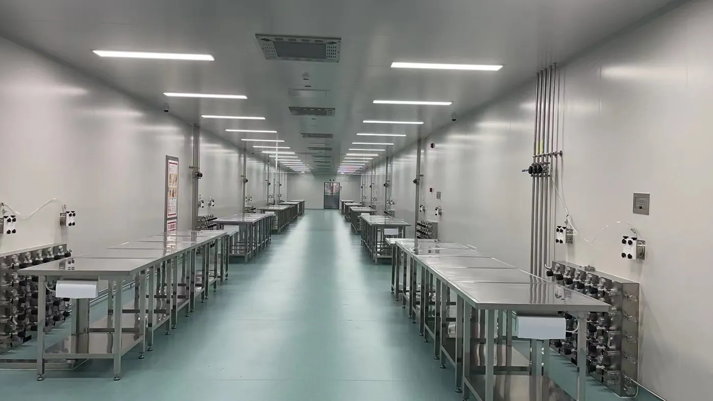
A university laboratory is rarely a fixed production line. A room may support a doctoral project this year, a visiting research group next year and a different instrument after the next grant cycle. Gas demand changes with those decisions. A practical university research laboratory gas supply plan therefore begins with the people, experiments and equipment that will share the building. It sets a clear boundary between a common laboratory gas distribution system and the local connections each research group is allowed to change. The result should help researchers work without turning every instrument move into an undocumented pipe modification.
This page addresses research buildings, teaching laboratories and shared analytical facilities. It is an application guide rather than a generic centralized gas supply specification. The useful question is how to combine flexible point-of-use service with source control, gas segregation, training and a maintained record of what each outlet supplies. The exact gas list, hazard controls and local code requirements must be reviewed for the site. A building-wide manifold may suit common inert gases; a short dedicated line or a specially controlled cabinet may be the better answer for a niche research gas.
01 / RESEARCH BRIEF
Map instruments, users and the pace of change
Start with a room-by-room gas-use schedule. Record each instrument, gas or mixture, cylinder connection, required inlet purity, operating pressure, normal and peak flow, run duration, expected expansion and owner. Include bench instruments, shared core facilities and intermittently used pilot equipment. A list that says only “nitrogen, argon and hydrogen” hides the details that drive line size and control: a high-flow purge, a sensitive carrier-gas application and a low-flow calibration standard can require different arrangements even when they use the same nominal gas. Ask instrument owners for current installation manuals rather than inheriting a pressure value from an old drawing.
Record who can authorize a new use point, a cylinder change and a change in gas service. Universities often have overlapping responsibilities among researchers, departmental staff, campus facilities and environmental health and safety. The system design should make those boundaries visible at the cylinder room, manifold, distribution shutoffs and each terminal. This matters in shared laboratories where a person may operate an instrument without knowing who owns the upstream gas train. A simple, current equipment schedule and marked isolation map can be more valuable in daily operation than a complex control panel nobody is assigned to maintain.
02 / SHARED SOURCE
Separate common utilities from specialist gases
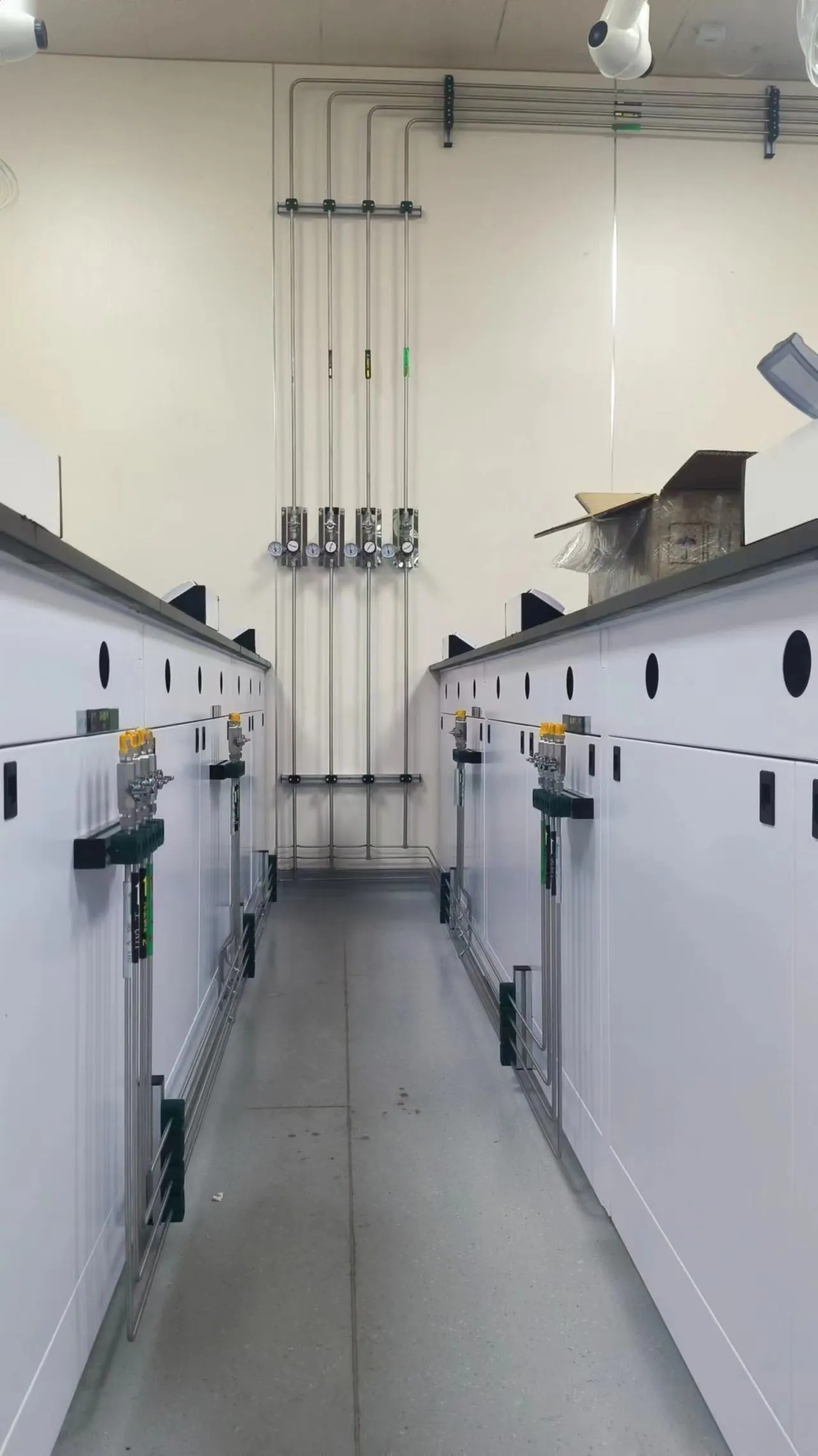
Common laboratory nitrogen, argon or instrument air may justify a centralized source when many rooms use them and a stable, managed supply simplifies operations. Estimate simultaneous demand, route length, source-change frequency and how interruptions affect experiments before selecting a bank manifold or automatic changeover. A central source reduces scattered cylinder handling, but it also concentrates the consequences of a header fault. Provide an isolation strategy that allows one branch to be maintained without unnecessarily stopping unrelated research. The branch schedule should show which rooms actually need uninterrupted service and which can tolerate a controlled shutdown.
Specialty mixtures, corrosive gases or short-lived research requirements should not be pulled into a common header just because spare pipe capacity exists. Their containment, purge, compatible materials, ventilation and decommissioning needs may be different. Review the chemical and physical hazards with the campus safety team and document why the chosen source location is appropriate. A high-purity laboratory gas system is only as clean as its cylinder connection, regulator, valve, tubing and point-of-use fitting. The source specification should match the experiment rather than promise one purity level for the entire building.
03 / DISTRIBUTION
Give shared rooms a legible and adaptable gas path
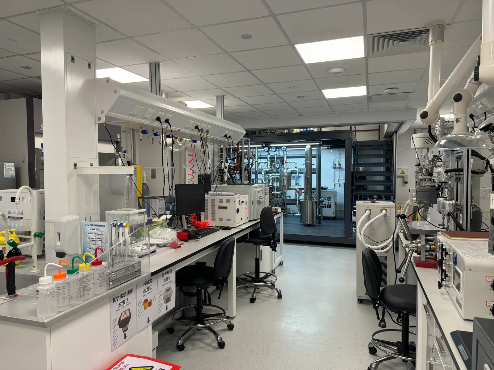
A research laboratory gas distribution system needs identifiable routes, accessible isolation valves and reserved service space. Coordinate pipe routes with ceilings, fume exhaust, electrical trays, fire separations and future lab renovations. A drawing should trace each gas from its source to the end outlet, identify pressure boundaries and show where branches can be safely isolated. Size the route using the expected simultaneous duty and pressure drop, including the final flexible connection where applicable. Oversizing every branch can increase stagnant volume; undersizing can leave instruments outside their specified inlet range when several experiments run together.
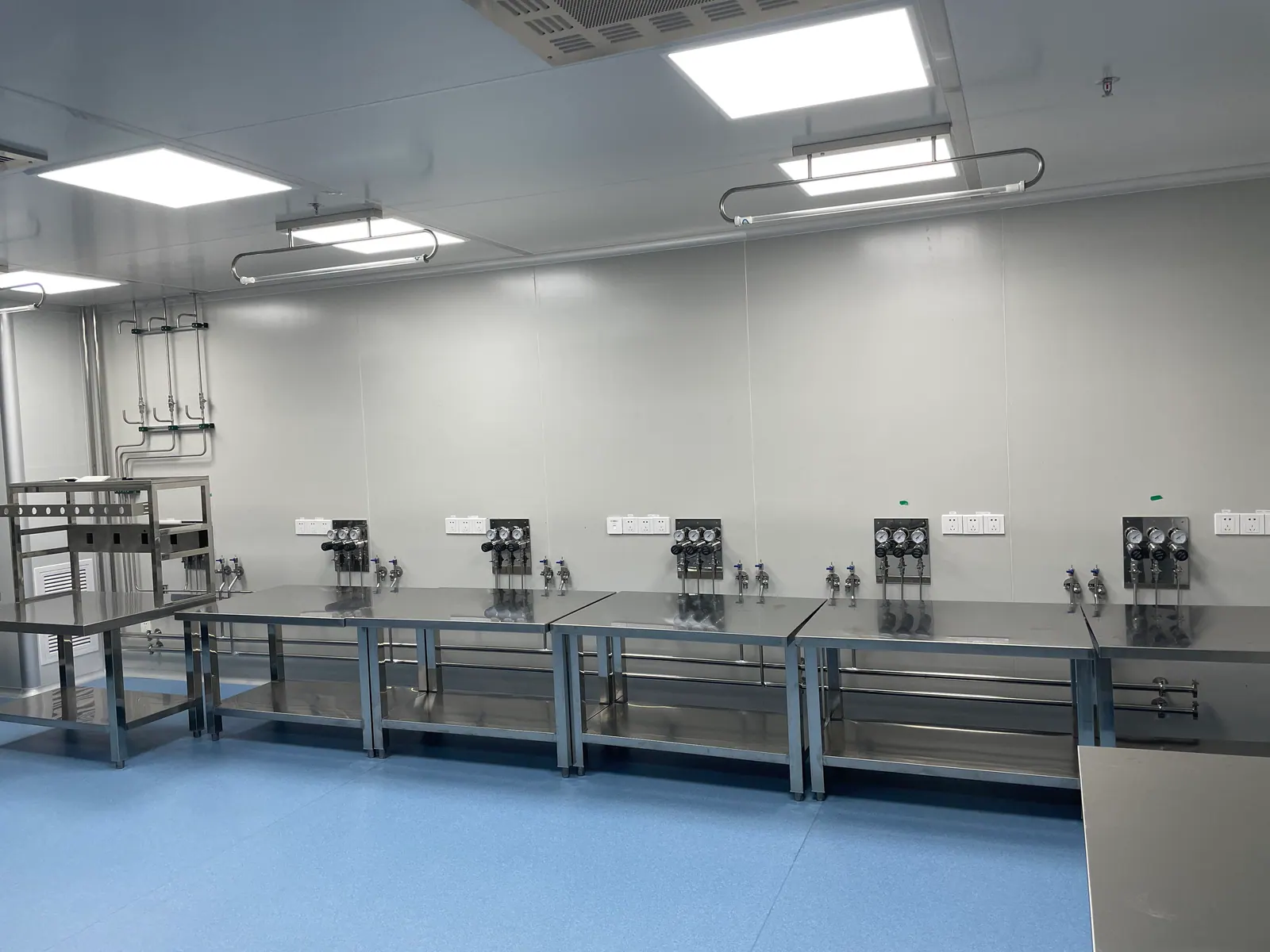
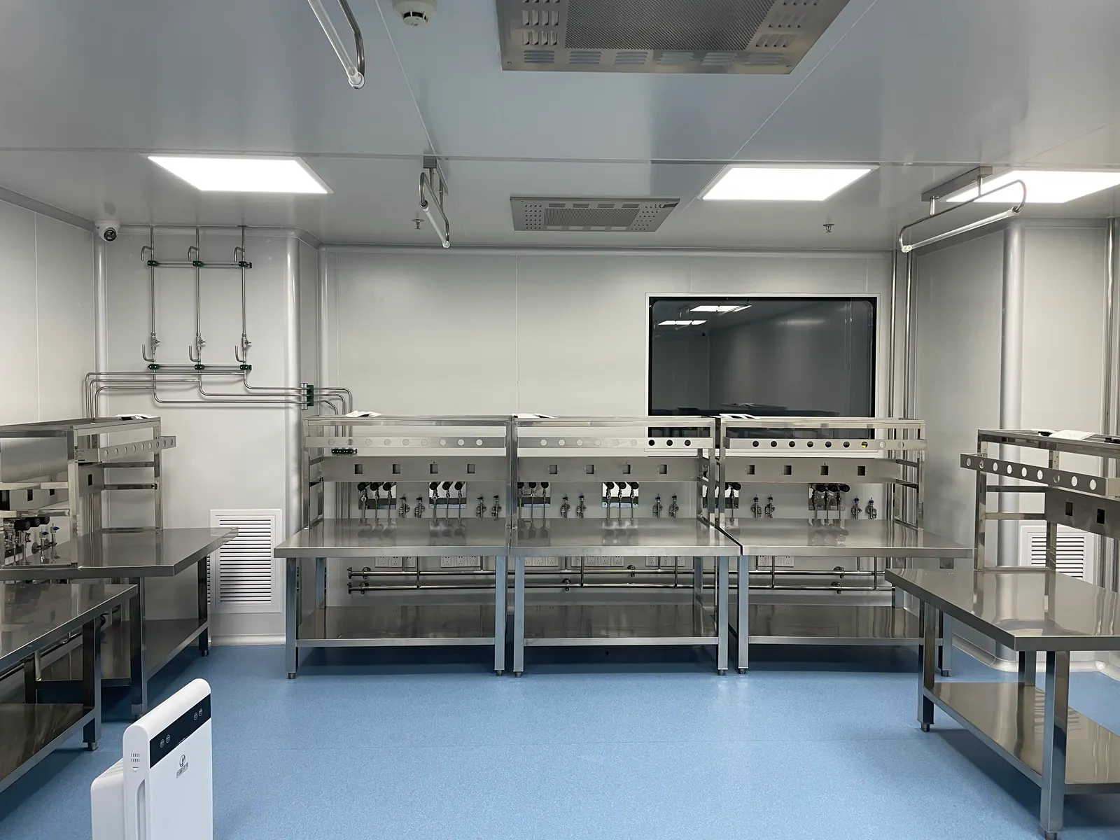
At the bench, point-of-use laboratory gas panels should make the gas identity and local pressure clear. A terminal that looks interchangeable may tempt a new user to connect the wrong instrument or adjust a shared regulator. Label outlet service, pressure range, shutoff function and the responsible contact. If rooms will be reconfigured, provide a controlled change process: verify the new instrument requirement, assess gas compatibility, update the drawing and test the altered branch before use. Flexibility comes from planned interfaces and documentation, not from leaving unused live outlets untracked.
04 / EXPERIMENT QUALITY
Protect gas quality where the experiment needs it
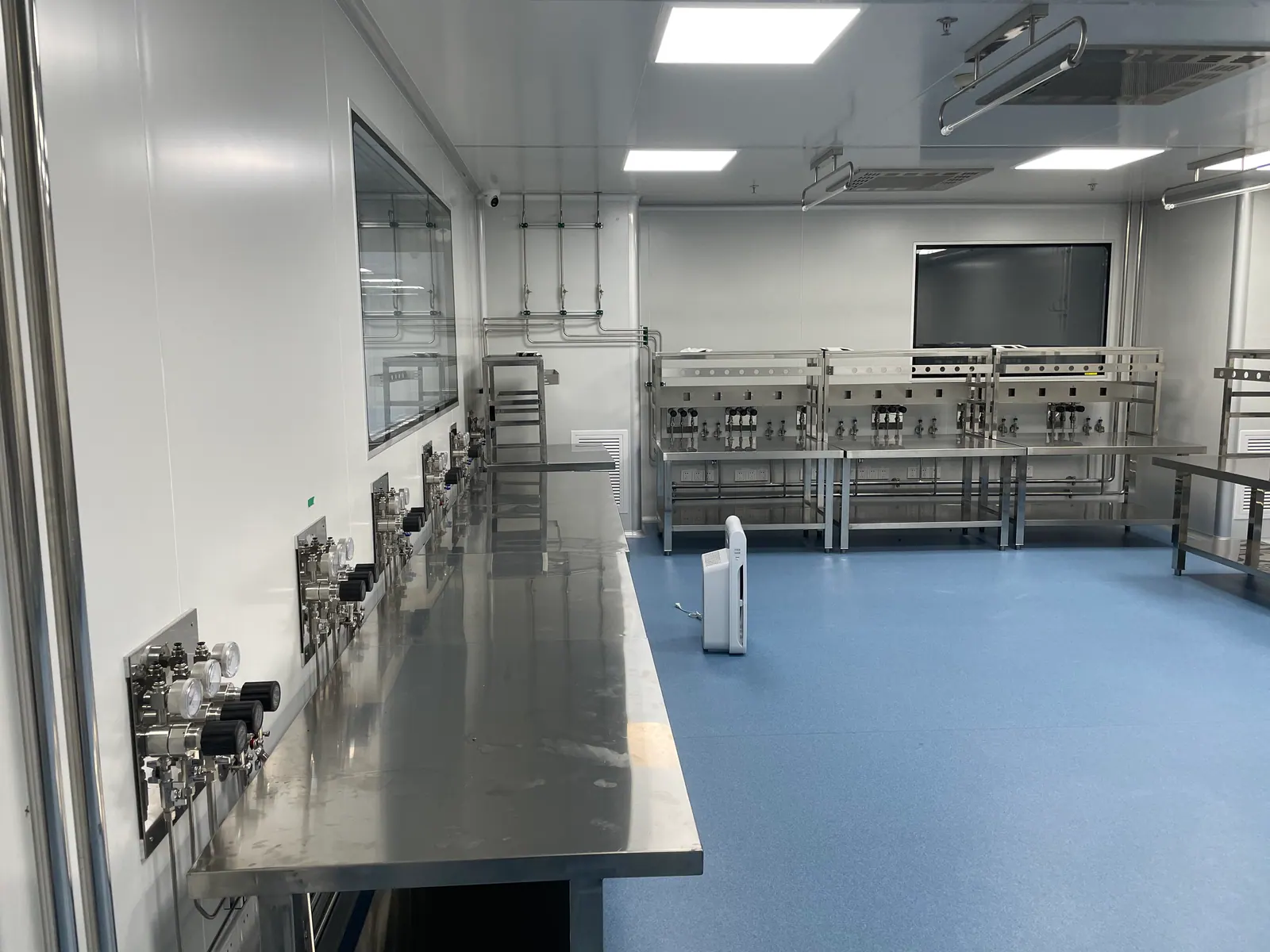
Analytical instruments and research processes may be affected by moisture, oxygen, hydrocarbons or particles carried into the line during installation or cylinder change. Define the required delivered gas quality at the instrument, then work backward through the source grade, regulator design, wetted materials, sealing method and line-cleaning practice. For a sensitive application, specify the measurement or acceptance method as well as the nominal cylinder grade. A cylinder certificate alone does not prove that a long, poorly protected downstream path delivers the same condition at the bench.
Plan for different research groups to have different thresholds. A general purge line and a trace-analysis carrier-gas line need not share the same component standard. Separate service classes on the drawing, prevent accidental cross-connection and provide a controlled procedure for opening a high-purity line. When selecting UHP gas regulators, diaphragm valves and stainless-steel fittings, confirm compatibility with the named gases and the research duty. These choices should be supported by instrument requirements and the facility maintenance capability, not by a broad claim that every research line must be built to the highest possible specification.
05 / SAFETY & PEOPLE
Coordinate alarms, access and laboratory training
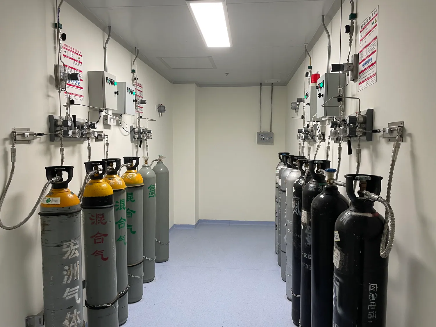
Shared buildings make gas safety a communication problem as well as an engineering problem. A flammable, toxic or oxygen-displacing release may require detection, ventilation response, source isolation and evacuation instructions. Sensor position and alarm sequence need a room-specific review; one detector in a cylinder room does not automatically protect an instrument area several floors away. State who receives an alarm, who may reset it, what valve changes state and how the event is recorded. The equipment supplier, building controls contractor and campus safety team need a common cause-and-effect matrix before commissioning.
Training must follow the system that was actually installed. Operators should know how to identify a gas outlet, recognize abnormal pressure, report a leak concern and avoid bypassing an interlock. Facilities personnel need a controlled cylinder-change and maintenance process. Incoming students and visiting researchers need a short handover that fits their role. Tsinghua University’s published account of its centralized supply launch emphasizes that operation training remains essential after installation; that is a useful reminder that a central system does not remove the need for local ownership and routine checks.
06 / HANDOVER
Commission for the next research team, not only opening day
The acceptance package should identify line service, component and material records, pressure and leak-test boundaries, purge or cleanliness method where specified, regulator set points, alarm tests and as-built drawings. Test each point of use against its documented gas and pressure requirement. Demonstrate source changeover and maintenance isolation under a controlled procedure. Leave room for the research team to witness instrument startup, since a pipework test alone cannot establish that an instrument receives the necessary pressure and gas quality during operation.
Plan who updates the record when a grant brings in new equipment, a lab moves or a gas is retired. Decommissioning should include a positive check that the line is isolated, purged and relabeled before it becomes available for another use. A university gas supply system is successful when the next group can understand its limits without reverse-engineering the ceiling. For procurement, share the room schedule, gas list, utility boundaries and available building drawings so that source equipment, laboratory gas piping components and terminal panels can be quoted against the real duty.
PLANNING IN PRACTICE
Decisions to resolve before the specification is fixed
Multi-department governance
A shared research building needs a utility owner even when its laboratories belong to separate departments. Establish a campus-level outlet register with gas, location, pressure class and authorized user. The register should be accessible to the team that approves an instrument move and to the team that responds to a source alarm. Without it, a new lab group can inherit a line whose original purpose has disappeared from the room drawing. Assign an update step to each space handover, not only to major construction projects.
A practical review meeting brings the principal investigator, instrument specialist, facilities engineer and safety representative together around one annotated plan. Their questions differ: the researcher needs experimental flexibility, facilities needs maintainable valves and safety staff needs a defensible hazard boundary. Recording decisions and unresolved items prevents a contractor from making a design choice by default. The same record helps procurement compare offers against the same scope rather than against differently assumed gas lists.
Research continuity
Some research tools can be restarted after a short gas outage; others may lose a long experiment or a valuable sample. Classify the consequences before specifying reserve cylinders and automatic changeover. A building-wide “no interruption” statement can drive cost without identifying which branches actually require continuity. Consider source lead time, planned shutdowns and the ability to move work to another instrument. Where uninterrupted supply matters, test the alarm path and the spare-bank procedure with the staff who will respond after hours.
A simple operating dashboard can show source pressure and alarms, but it needs a response owner. Define what counts as low reserve, how quickly a replacement can arrive and whether a researcher may continue a run. Separate the emergency shutdown function from a convenience warning. This helps laboratories avoid both unnecessary evacuations and the opposite problem: repeatedly acknowledging an alarm until a critical supply is exhausted.
Future expansion
University buildings change in stages. Reserve space for future source capacity and plan controlled tie-in points, but do not leave unidentified live gas outlets awaiting an unknown experiment. A capped branch should have a recorded status and a test requirement before activation. Consider the route to prospective shared rooms; a future core instrument may have a different pressure or purity duty from current benches. The ability to add a line cleanly can be more useful than installing a large universal header that later proves incompatible with specialist gases.
When a department renovates one floor while others remain occupied, the isolation map determines how widely work must stop. Ask installers to document valve function and to demonstrate a safe branch shutdown. Include contamination controls for opening a high-purity line and a communication plan for users who may be affected. The resulting system supports phased growth while keeping old and new research services understandable.
Instrument handoff
A laboratory gas system should deliver the specified condition to an instrument connection, but instrument start-up still belongs to the equipment team. Define the fitting, hose, pressure gauge location and measurement point in the handoff sheet. Some instruments include internal regulators or purification; others assume that the facility provides them. If both teams assume the other supplies the final stage, the problem appears only at installation. Obtain current model-specific manuals and update the gas schedule when equipment is replaced.
During acceptance, involve the intended users in a walkthrough. Verify that they can identify the correct terminal, read its pressure, recognize a closed valve and find the local isolation. That walkthrough may reveal labels hidden behind a new bench or a regulator mounted too high for routine checks. These are inexpensive fixes before occupation and persistent sources of confusion afterward.
Lifecycle cost
Compare a proposed centralized laboratory gas supply against local cylinders over the likely life of the building, not just the initial equipment price. Include cylinder handling, change frequency, rental, installation access, detector calibration, maintenance, planned downtime and documentation. Some low-use gases may remain economical as controlled local sources. Common utilities may justify central supply when many rooms rely on them and routine handling is significant. The design should articulate the threshold rather than claim that centralization is always cheaper.
Ask bidders to separate source equipment, distribution, terminals, controls integration, testing and user training. This exposes exclusions and allows phased purchase decisions. Include spare components and maintenance instructions in handover so that a small part failure does not require reverse-engineering the system. The purchasing question is whether the arrangement remains manageable when research groups and staff change, not whether its first-day component list is impressive.
DESIGN REVIEW
Practical checks that protect the full gas path
Shared instrument rooms
Allocate capacity by likely simultaneous use, not by simply adding every instrument nameplate flow. Agree which experiments can run together and which need a reserved source. Document the assumption so that future instrument purchases trigger a capacity check.
Teaching versus research
Teaching benches may need robust, easily supervised outlets and clear shutdown. Research benches may need more unusual gases and stricter purity. Treat them as different service classes even when they occupy the same department.
Cylinder logistics
Consider delivery routes, restraint, changeout space, supplier connection and how a depleted cylinder is identified. Unplanned bottle movement through occupied corridors can undermine the advantage of centralized distribution.
Phased renovations
Mark safe tie-in locations and future valve positions, but keep unused outlets isolated and documented. A planned branch extension is easier to inspect and commission than a field-added tee whose service is unclear.
Responsibility matrix
Name the owner for source changes, alarm response, detector calibration, regulator maintenance, line modification and user training. A building system can cross several university departments without any one of them owning the whole path.
Budget scope
Compare proposals using the same gas schedule, outlet count, source duty, test requirements and building interfaces. A low component quote may omit installation access, controls integration or commissioning that the project still needs.
Utilities at the bench
Confirm bench height, instrument location and the user’s sightline before fixing a terminal. A pressure gauge hidden behind an instrument is difficult to monitor. If a bench is shared by several groups, label which valve serves which connection and whether closing one outlet affects its neighbor. Walk the room plan with actual equipment dimensions.
Alarm escalation
Map a source or room alarm to an action, a person and an after-hours contact. A building-management notification may reach facilities but not the experiment owner. An audible alarm may warn occupants but provide no technical diagnosis. Test each route during handover and repeat the test after staff or room responsibilities change.
Service-class labels
Separate general utility gases, high-purity analytical lines and hazardous specialty gases in the register and physical labels. The classification should drive cleaning, maintenance and connection rules. A color alone is a poor substitute for a gas name and pressure range, especially when different projects have reused the same bench.
Shutdown planning
Publish a shutdown notice that names affected rooms and instruments, not only a valve number. Give researchers time to finish long runs or protect samples. After work, verify that each affected outlet has been restored to the expected gas and pressure. Record any branch left isolated rather than assuming all rooms are back in service.
Training evidence
Keep concise records of who can change cylinders, authorize modifications and respond to an alarm. Training for a visiting researcher can focus on terminal recognition and incident reporting; specialist maintenance requires more. The purpose is to make the installed arrangement usable as personnel turn over, not to replace the institution’s broader laboratory safety program.
START THE PROJECT CONVERSATION
What to send for a university gas-system review
A useful technical proposal starts with operating conditions and a clear division of responsibility. Send the information available today; unresolved items can become design-review questions.
- Building and room plans with current and planned instrument locations
- Gas list with purity, pressure, flow and hazard information for each use point
- Existing cylinder, manifold and distribution drawings if available
- Research groups, shared-room users and responsibility for maintenance
- Future equipment plans, phasing and shutdown constraints
- Campus safety, ventilation, alarm and building-control requirements
FREQUENT QUESTIONS
Questions to settle before equipment selection
Should every research gas be centralized?
No. Centralize a gas when shared demand, source management and route make that practical. Keep specialist or short-term gases separate when their hazard, purity or change pattern calls for a dedicated arrangement.
How do we preserve flexibility for new instruments?
Use a documented service schedule, accessible isolation and a formal modification process. A new instrument still requires a compatibility, capacity and acceptance check before connection.
Is one regulator setting enough for all labs?
Usually not. The source and distribution pressure should support the network, while local regulation can match each instrument. The final design must follow the actual pressure and flow schedule.
What should be in the handover package?
At minimum, as-built gas routes, outlet schedule, test records, alarm sequence, source-change instructions, maintenance responsibilities and training records appropriate to the facility.
TALK TO LGF Lab Gas Flow
Turn the gas-use schedule into a reviewable equipment scope.
Share the room plan, instrument list, gas requirements and building interfaces. We can help define source control, distribution and point-of-use equipment for your laboratory.