
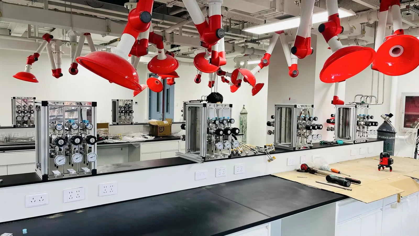
APPLICATIONS / ENVIRONMENTAL ANALYSIS
Environmental Monitoring & Analytical Laboratory Gas Supply
A source-to-instrument gas plan for environmental samples, trace analysis and changing analytical workloads across the laboratory.
APPLICATION OVERVIEW
Begin with the way this laboratory actually works
Environmental and physicochemical laboratories analyze air, water, soil, waste and process samples using different methods and different gas utilities. One room may need argon for an ICP instrument, another helium or hydrogen for gas chromatography, and a separate bench may need nitrogen or clean air for preparation and detection. The environmental analytical laboratory gas supply must match the real analytical method and instrument configuration, not a generic list of gases used somewhere in the building. Pressure stability, gas cleanliness and an identifiable connection can affect measurement reliability and instrument availability.
This application page concentrates on the relationship between analytical workflows and utility design. It is distinct from the independent testing page, which focuses on multi-client operations and continuity across a broad test portfolio. Here the planning lens is method-specific gas quality, calibration and source-to-instrument performance for environmental work. Instrument manuals and the laboratory’s approved methods remain the authority for numerical requirements. A gas-system supplier can coordinate the delivery hardware but should not replace method validation, analytical QA or a site-specific safety assessment.
01 / METHOD INVENTORY
Start from methods and instruments, not a standard gas list
Build a method-to-gas matrix. For each GC, GC-MS, ICP-OES, ICP-MS, TOC, atomic absorption or other gas-dependent instrument, list the exact model, method, gas role, inlet connection, purity, pressure range, flow and operating schedule. Include calibration and blank runs where gas quality can affect the result. A method may use a gas as carrier, plasma, reaction, make-up, purge or detector fuel; those roles are not interchangeable. The manufacturer’s current site-preparation material should be checked against the laboratory’s validated method before a line or regulator is specified.
Environmental programs can have seasonal or project-driven sample surges. Note which instruments run simultaneously and how long a cylinder or bulk source must support the queue. Map the analytical rooms and any remote source location. A laboratory gas distribution system should have enough capacity for concurrent demand at the farthest use point without unnecessarily sharing a sensitive carrier-gas line with a high-flow utility. Where an instrument changes model or method, review the utility schedule before connecting it to an existing terminal.
02 / ICP SERVICES
Keep plasma and auxiliary-gas supply within the instrument envelope
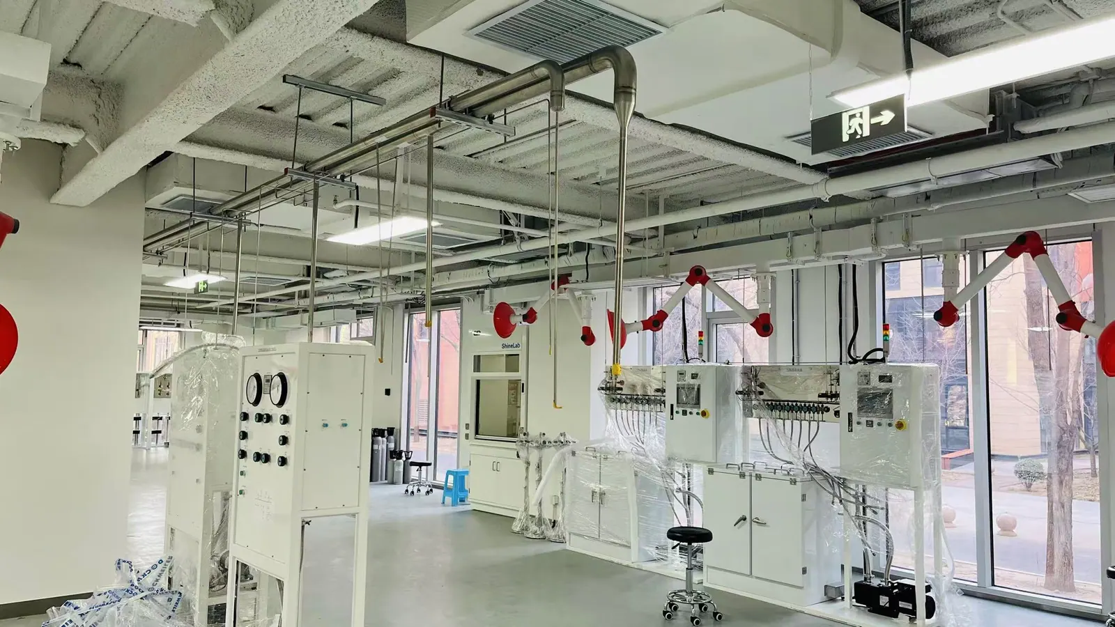
ICP instruments can consume substantial argon during long analytical sequences. Their source and regulator selection should be based on the particular model’s pressure, purity and flow specification, expected run hours and available reserve. If additional reaction or collision gases are used, they may need their own low-flow high-purity path and more precise pressure control. Published ICP-MS installation guides from Agilent and Thermo Fisher show that requirements differ by instrument and accessory; do not carry one manufacturer’s values into another model without checking.
A long route from an external source needs a pressure-drop assessment that includes peak demand and source changeover. Define what indication operators need when reserve is low and how the system behaves during a cylinder or vessel change. Keep high-flow plasma supply separate from small specialty-gas channels when the instrument demands it. Coordinate the final connector and regulator with the instrument owner; the building utility should deliver the specified condition at the inlet, not merely at the source panel.
03 / CHROMATOGRAPHY
Protect carrier and detector gases from the whole-path contamination risk
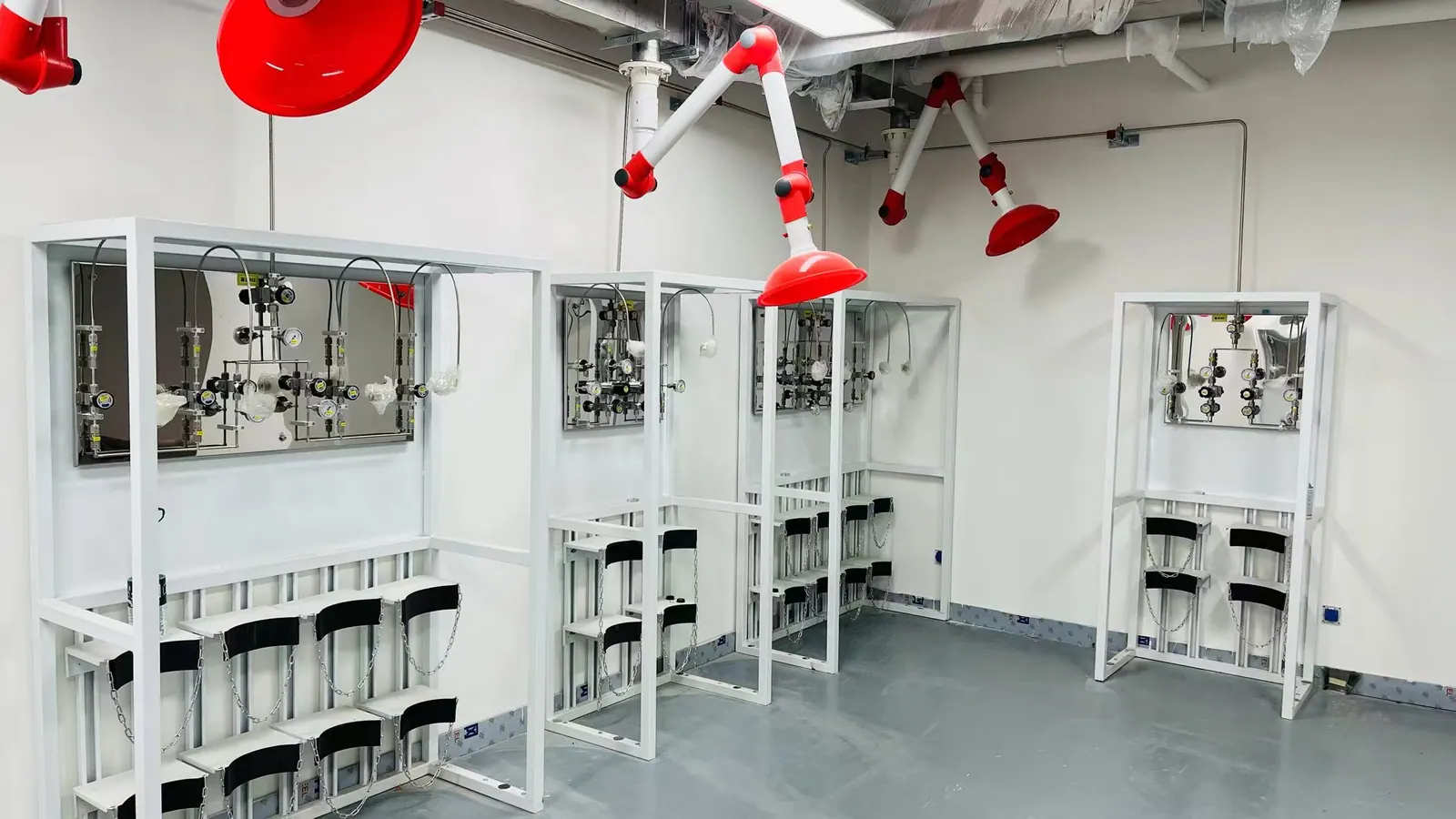
GC and GC-MS methods can be sensitive to oxygen, moisture or hydrocarbons introduced downstream of a nominally pure cylinder. Specify the required delivered gas quality at the instrument and review the cylinder connection, regulator, valves, tubing, joints and any purification. A laboratory nitrogen, hydrogen or specialty gas system needs separate review for each analytical role. A carrier-gas requirement should not be generalized to a detector fuel or an instrument-air supply. The choice of gas and purity belongs to the method and equipment instructions.
Design the route for maintenance as well as initial cleanliness. Every cylinder replacement, filter change or opened fitting can introduce contamination if the return-to-service procedure is weak. Define leak checks, purge and any method-specific verification before analytical runs resume. Do not hide a tee or hose behind a bench where it cannot be inspected. A clear point-of-use panel with labeled isolation and pressure indication makes it easier for an analyst to distinguish an instrument fault from an upstream utility problem.
04 / CALIBRATION
Keep reference gases identifiable and separate from routine utilities
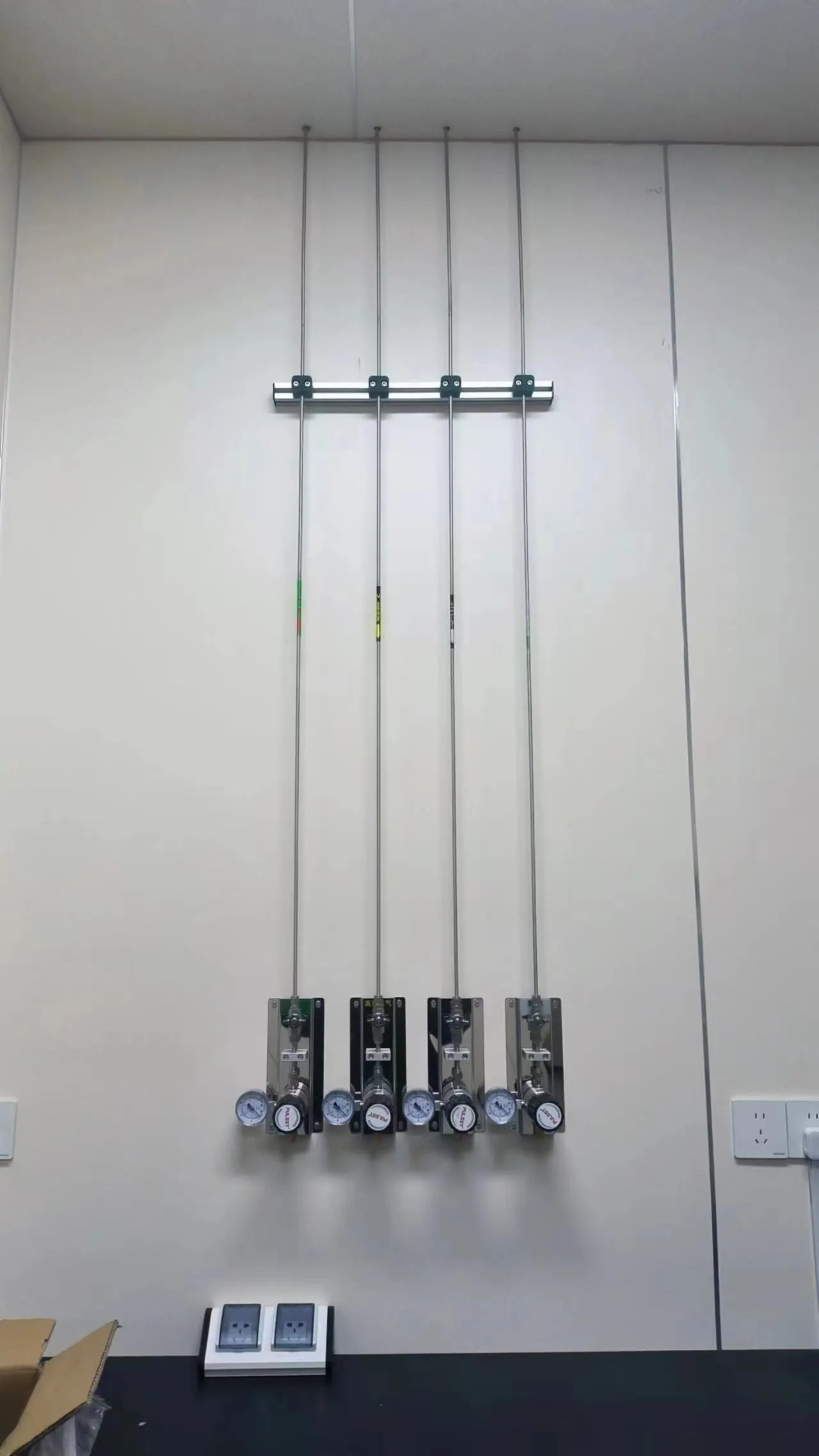
Environmental measurements may rely on calibration mixtures and certified reference gases. Their cylinder identity, expiration, concentration and permitted connection are analytical quality matters. The gas distribution design should allow controlled access and a traceable route without implying that a manifold certifies the mixture. Avoid combining different reference standards into a shared header unless compatibility and carryover risks have been reviewed. A dedicated short connection may be better than a long centralized line for a rarely used mixture.
Where zero air, nitrogen or another blank-support gas is used, define how its quality is confirmed at the instrument. A high-purity source can be compromised by an unsuitable hose or a regulator that has served a different gas. Label all calibration and support outlets with gas identity and service range. Keep a record of which instrument was connected, especially in rooms where equipment is moved between studies. This makes troubleshooting more efficient when a blank rises or a calibration sequence fails.
05 / SAFETY & ROUTING
Integrate source management with the laboratory layout
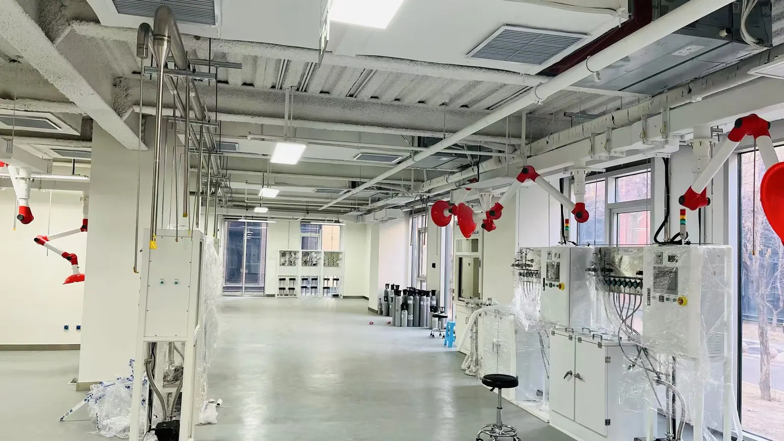
Environmental laboratories often concentrate several analytical instruments in a limited space. A centralized gas supply can reduce cylinders beside workbenches, but it creates a distribution route that must be identified, protected and isolatable. Plan cylinder access, restraint, changeout and ventilation with the facility safety team. Hydrogen, oxygen-displacing gases and any hazardous mixture require their own hazard review; the detector, alarm and isolation design must follow the actual gas and room. Avoid assuming that a general laboratory exhaust system manages a particular gas release.
Keep tubing routes accessible and away from avoidable damage. Show which outlet is served by each branch, where pressure is reduced and where a room can be isolated for maintenance. A clear as-built drawing supports both emergency response and future instrument additions. If a corridor or ceiling route crosses building zones, coordinate it with the architect and services engineers early. The line should also have a practical means of leak testing and controlled purge after modification.
06 / VERIFICATION
Test delivery where analysis actually occurs
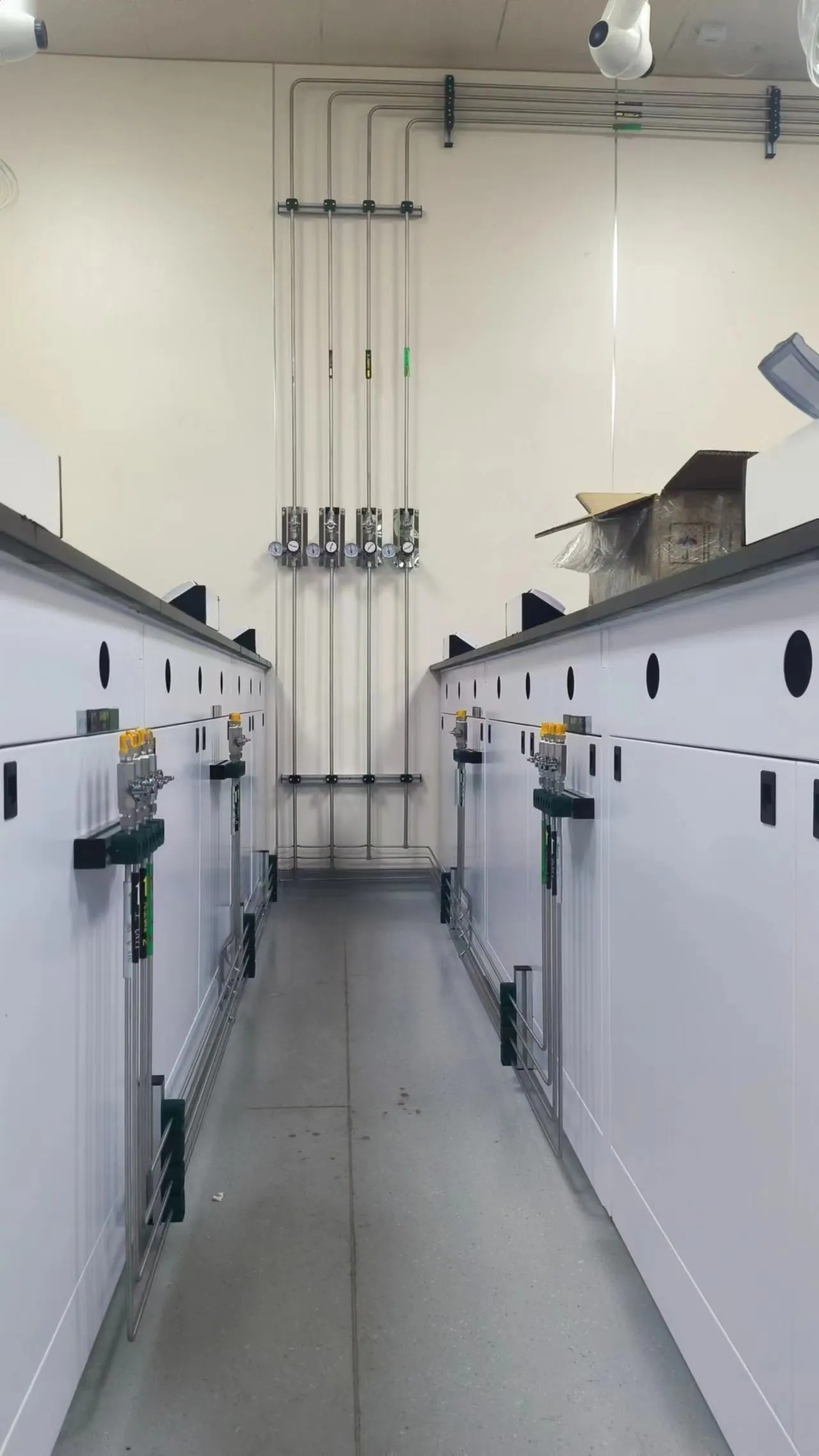
Commissioning should verify line identity, pressure and leak integrity, regulator function, alarms where fitted, and instrument inlet conditions under representative concurrent operation. For sensitive methods, agree how delivered cleanliness will be assessed. Record the source, terminal and final connection that were tested. Pressure at a cylinder-bank gauge does not demonstrate the same pressure at the last instrument during a high-flow run. Likewise, a clean source certificate does not show that the installed line remained clean after fabrication.
Hand over a gas-use matrix, outlet map, source-change procedure, alarm instructions and maintenance log. Include a review trigger when analytical methods, instrument models or sample volume change. This turns laboratory gas piping into a managed utility rather than an invisible installation. For a useful quotation, provide instrument site-preparation guides, room layout, required operating hours and the test evidence the laboratory expects. LGF Lab Gas Flow can then align source controls, high-purity components and point-of-use stations with the real analytical workload.
PLANNING IN PRACTICE
Decisions to resolve before the specification is fixed
Sample matrix differences
Air, water, soil and waste samples can drive different analytical methods, preparation steps and instrument loading. The gas-system schedule should follow the methods actually used at the site rather than the laboratory’s general environmental label. A trace-metals ICP room may consume argon continuously during a campaign, while a chromatography room may need low-flow but very clean carrier gas. Plan each separately, then review whether any common source is sensible. Treat future analytical techniques as a change request, not an assumption hidden in the initial pipe size.
Ask analysts which supply variations have previously interrupted runs or affected blanks. Their answers can identify pressure, source-change or contamination risks that a floor plan cannot reveal. Use those observations to set acceptance criteria, while checking them against manufacturer documentation and the laboratory’s approved method.
Traceability of standards
Calibration and reference mixtures often have a short chain of custody from supplier package to instrument. The utility design should help analysts identify the active mixture and avoid unintended cross-connection. If several standards are used on one instrument, define the approved switching and purge method. Do not route a low-use standard through a large shared header without assessing residence time, compatibility and carryover. The gas control hardware supports traceability but cannot substitute for the method’s certified-reference-material process.
Document the final connection and authorized operator. A cylinder may be moved between methods while its regulator remains attached; record whether that regulator and hose are suitable for each service. A clear storage and labeling arrangement reduces the chance of using the wrong concentration during a busy sampling campaign.
Cleanliness and blank response
A rising analytical blank may point to a contaminated reagent, instrument component or gas path. The gas design should allow the laboratory to check delivered gas at a relevant point and isolate branches without taking the whole building offline. Where inline purification is used, identify replacement intervals and any breakthrough indication. Keep maintenance openings accessible and protected from ambient air. Document the purge and verification needed after a filter or regulator replacement.
Avoid setting one generic purity threshold for every method. An ICP plasma gas, GC carrier gas and sample-preparation nitrogen stream can have different contaminant concerns. The right specification is the one supported by the instrument and analytical method at the use point.
Campaign capacity
Environmental monitoring work can arrive in bursts after an incident, seasonal program or regulatory deadline. Model the most likely simultaneous instrument schedule and the source replacement lead time. A reserve bank should be sized to cover the period in which a depleted source can realistically be replaced, not merely to make a changeover device cycle. Consider access outside ordinary working hours if overnight sequences are common.
Verify pressure at the farthest instrument while other branches run. A source gauge may look healthy while a small regulator or long branch creates a local shortfall. Record the conditions of the test so a future instrument addition can be compared with the original design capacity.
Method and utility handoff
The laboratory should own the acceptance of analytical performance, while the gas-system team owns the documented delivery boundary. Agree on the exact inlet point and the measurement that demonstrates utility compliance there. If an instrument includes a purifier or regulator, define what the facility must supply upstream. If a new method asks for another gas, check ventilation, compatibility and controls before connecting it.
Use the commissioning walkthrough to make labels, shutoffs and alarm instructions familiar to analysts. A visible, well-documented terminal reduces troubleshooting time when a sample sequence stops unexpectedly. It also gives the laboratory a practical basis for maintaining the gas service between major building projects.
DESIGN REVIEW
Practical checks that protect the full gas path
ICP reserve planning
Estimate argon use from the exact instrument and scheduled runtime. Low-source alarms and a practical replacement process may matter as much as the nominal manifold capacity.
Trace-analysis blanks
If a blank or baseline is affected, troubleshoot the entire path: source, regulator, purifier, tubing, fittings and final connection. Avoid replacing an instrument part before confirming utility conditions.
Mixed gas roles
A carrier gas, collision gas, plasma gas and calibration mixture may each need different pressure and cleanliness treatment. Separate them in the schedule even if their cylinders sit in one source room.
Sample surge
Check simultaneous operation during peak campaigns, not only normal daily use. A pressure drop at a distant instrument can appear only when another analytical line starts.
Cylinder change
Define who changes the source, which isolation is used and what verification is needed before a method resumes. A low-pressure alert without a response procedure offers little protection.
Method revision
Update the gas schedule when the method or instrument changes. A new detector gas can alter component compatibility, venting and the safety review.
Peak argon demand
ICP instruments may consume a large amount of argon during long sequences. Model the real schedule, cylinder or bulk-source capacity and change lead time. A reserve arrangement should cover a credible delay, and operators need a warning early enough to act without sacrificing a run.
Carrier-gas change
Changing a GC carrier gas can affect method performance and utility safety. Review regulator, line, purifier, pressure, flow, ventilation and instrument compatibility before making the change. The gas distribution plan should not assume that a new cylinder alone completes a method transition.
Blank investigation
A failed blank can have several causes. Keep a route map and maintenance history that allow analysts to inspect the source-to-instrument path systematically. Pressure stability, recent cylinder change, regulator service and final hose condition are useful checks alongside analytical consumables.
Calibration mixtures
Store and connect reference mixtures so concentration and identity remain clear. Different standards may need dedicated regulators or a controlled switching procedure. Avoid a shared line when carryover or residence time could affect the method. Record which package was active for a calibration sequence.
Space for access
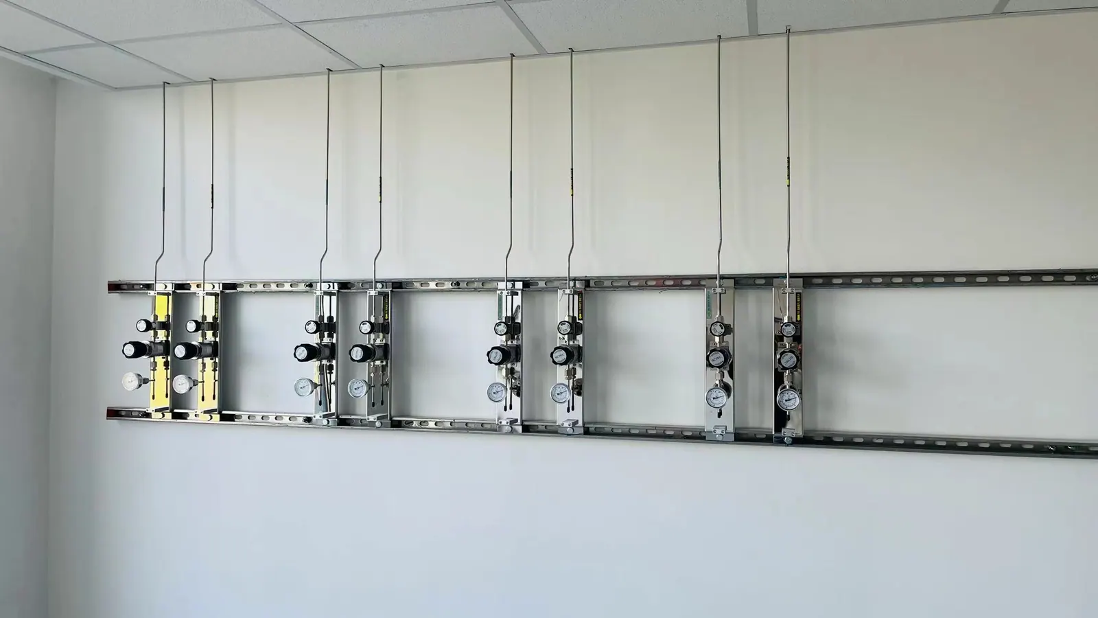
Analytical benches fill quickly with instruments and sample-preparation equipment. Place gas panels where labels, gauges and isolation can still be reached after the room is occupied. A well-positioned terminal reduces improvised long hoses and lets staff investigate a pressure warning without moving a delicate instrument.
START THE PROJECT CONVERSATION
Prepare an environmental analytical gas schedule
A useful technical proposal starts with operating conditions and a clear division of responsibility. Send the information available today; unresolved items can become design-review questions.
- Instrument models and current installation guides
- Approved methods and each gas role, purity, pressure and flow
- Daily and peak operating hours with concurrent-use assumptions
- Source room, cylinder logistics and reserve expectations
- Calibration mixtures and blank-support gases
- Accepted outlet, alarm and delivered-quality verification methods
FREQUENT QUESTIONS
Questions to settle before equipment selection
Can GC and ICP share one gas manifold?
They often use different gases, flow profiles and purity controls. Even where a nominal gas matches, a shared header needs a compatibility and simultaneous-demand review.
Where should purity be specified?
At the point required by the method and instrument. Source grade is one input; the regulator, tubing and final connection can alter delivered quality.
Does every environmental instrument need UHP components?
No. Choose the component standard from the method, instrument requirement, gas hazard and maintenance plan. Avoid both under-specifying sensitive lines and over-specifying general utilities.
What changes require a gas-system review?
New instruments, method gases, pressure ranges, source locations, routing, control settings or modified branches should trigger a documented review and return-to-service checks.
TALK TO LGF Lab Gas Flow
Turn the gas-use schedule into a reviewable equipment scope.
Share the room plan, instrument list, gas requirements and building interfaces. We can help define source control, distribution and point-of-use equipment for your laboratory.