
LGF / TECH SUPPORT
Laboratory Specialty Gas Installation Guidelines
Installation quality is decided before the first tube is joined. Follow the approved gas list, route, material and test plan from source to the instrument outlet.
A PRACTICAL TECHNICAL GUIDE
What an installation guide must establish first
Laboratory specialty gas installation is not one universal pipework recipe. The gas, hazards, quality grade, operating pressure, room use and local jurisdiction determine the approved specification. This page is a project-planning guide for engineers, contractors and laboratory owners: it organizes the information and evidence needed to install a route and bring it into service. It is not a substitute for an approved design, qualified installers or applicable codes.
Before mobilization, agree on a gas-by-gas line list, source and outlet drawings, component materials, joining and cleanliness methods, isolation boundaries, inspection hold points and acceptance tests. A route that looks clear in a drawing can be constrained by existing services, occupied laboratories or inaccessible ceiling space. A coordinated survey and change plan reduce avoidable rework and help preserve traceability through construction.
01 / BEFORE INSTALLATION
Freeze the gas list and identify every interface
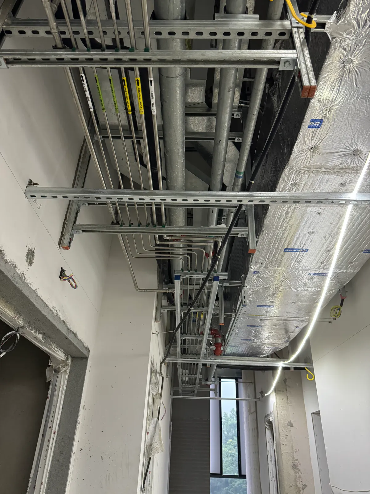
The installation package should name each gas and source, the required grade at the outlet, line size, pipe material, pressure range, route, isolation valves and terminal. It should also identify interfaces with ventilation, cabinet exhaust, detection, electrical controls, emergency isolation and building fire or access rules when they apply. An instrument schedule is needed to distinguish a high-purity analytical line from a utility or hazardous specialty service.
Contractors should verify existing conditions before cutting or connecting anything. Record the identity and status of old lines, access restrictions, wall or floor penetrations and services above ceilings. When work occurs in an operating laboratory, agree on shutdown windows, temporary barriers and return-to-service authority. An undocumented existing pipe cannot be assumed suitable for reuse.
02 / COMPONENT CONTROL
Protect approved tubing, valves and fittings
The material specification should address the actual gas and cleanliness requirement. Stainless steel laboratory gas piping may be appropriate for many high-purity services, but tube grade, finish, cleaning, caps, fittings and seals must be defined for the project. Components should remain identified and protected in storage and during movement through the site. Open ends invite moisture and particles into a line that may later serve a sensitive instrument.
A material receiving check compares delivered items with the approved schedule and confirms that substitutions have been reviewed. The installer should keep separate components for incompatible gases where the design requires it, and record batch or part information when traceability is specified. A visually similar fitting is not automatically equivalent in pressure rating, surface finish or material.
03 / FABRICATION
Use the joining method specified for the service
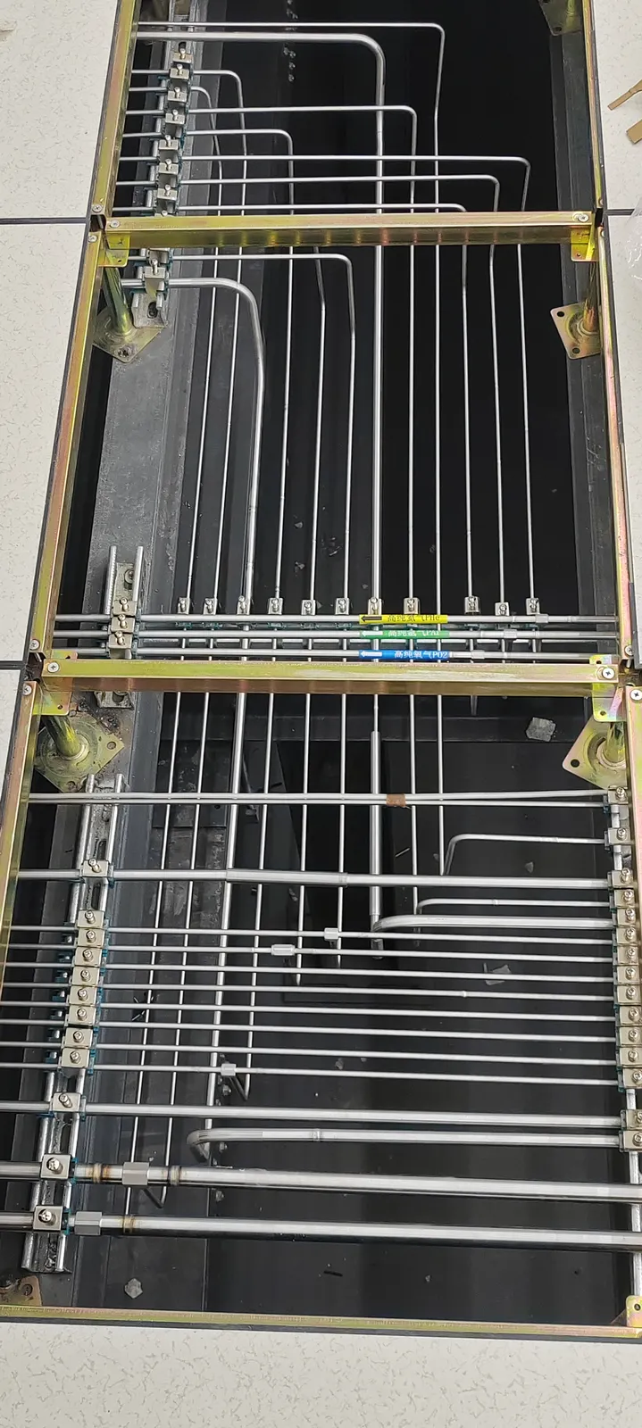
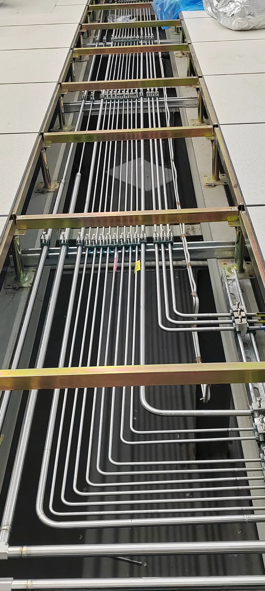
Welded and mechanical connections have different preparation, access and inspection needs. Where orbital welding for lab gas piping is specified, the approved procedure, fit-up, purge and record requirements should be defined before fabrication. Where compression fittings are specified, use the exact compatible components and manufacturer instructions. Neither method removes the need for a planned test of the completed section.
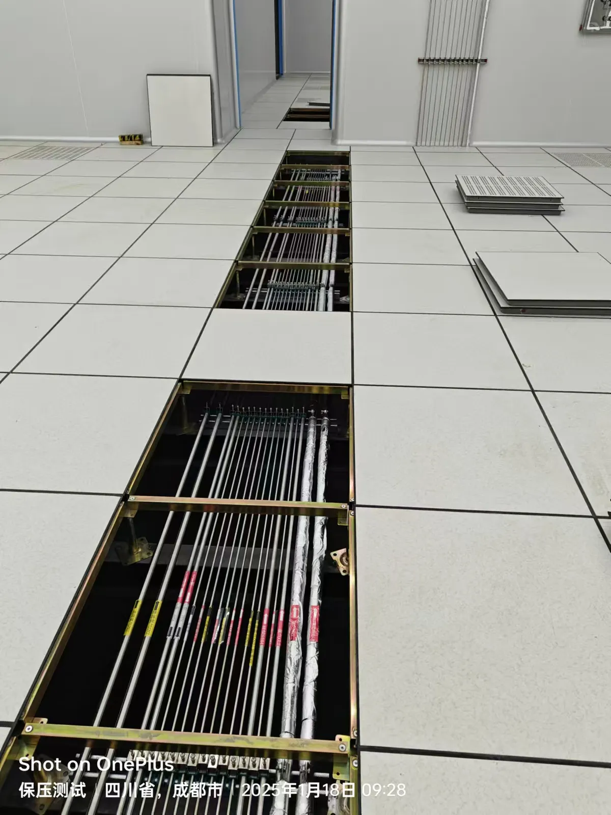
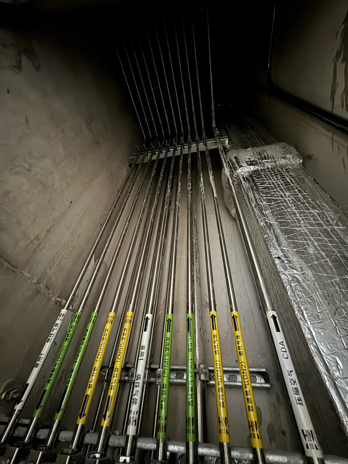
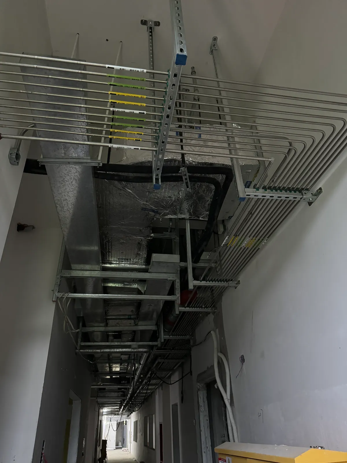
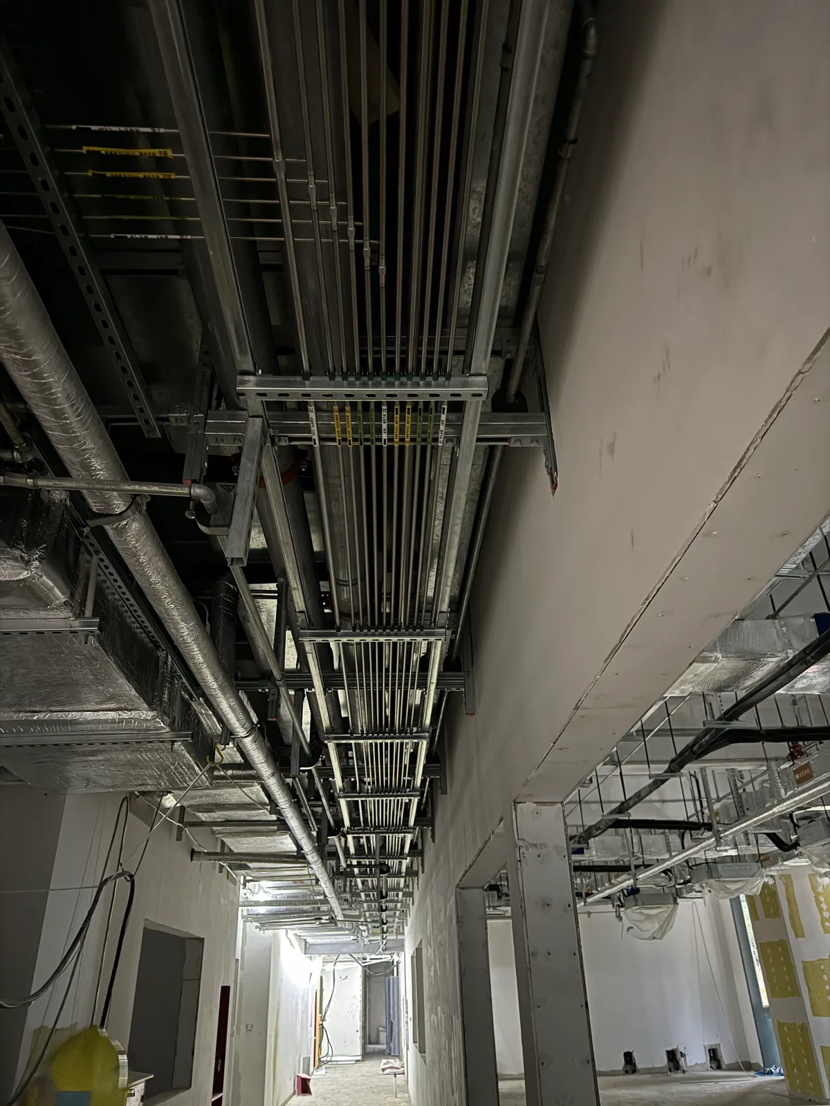
Supports and bends should avoid mechanical stress, preserve access and keep labels visible. The route should be checked against ducts, cable trays and maintenance zones as it is installed. Photograph concealed segments with location references before they disappear behind finishes; the photos complement, but do not replace, an updated as-built drawing.
04 / INSPECTION AND TESTING
Define tests before the pipework is closed
Inspection should confirm that each installed branch follows the approved drawing, uses the specified components and reaches the correct destination. Test methods and acceptance limits must be chosen for the gas, pressure and specification. Depending on the service, the plan may include pressure or leak testing, helium leak testing laboratory gas piping, cleaning, purge and delivered-condition checks. A generic pass statement is not enough without the method, boundaries, results and witness record.
Hazardous and high-purity lines may require additional controls, but these should be specified by the responsible engineer rather than inferred from the name of the gas. Test media, temporary connections and instrument protection need approval. Failed checks should be recorded, corrected and repeated under the same defined acceptance approach.
05 / BRING INTO SERVICE
Verify the source-to-instrument connection
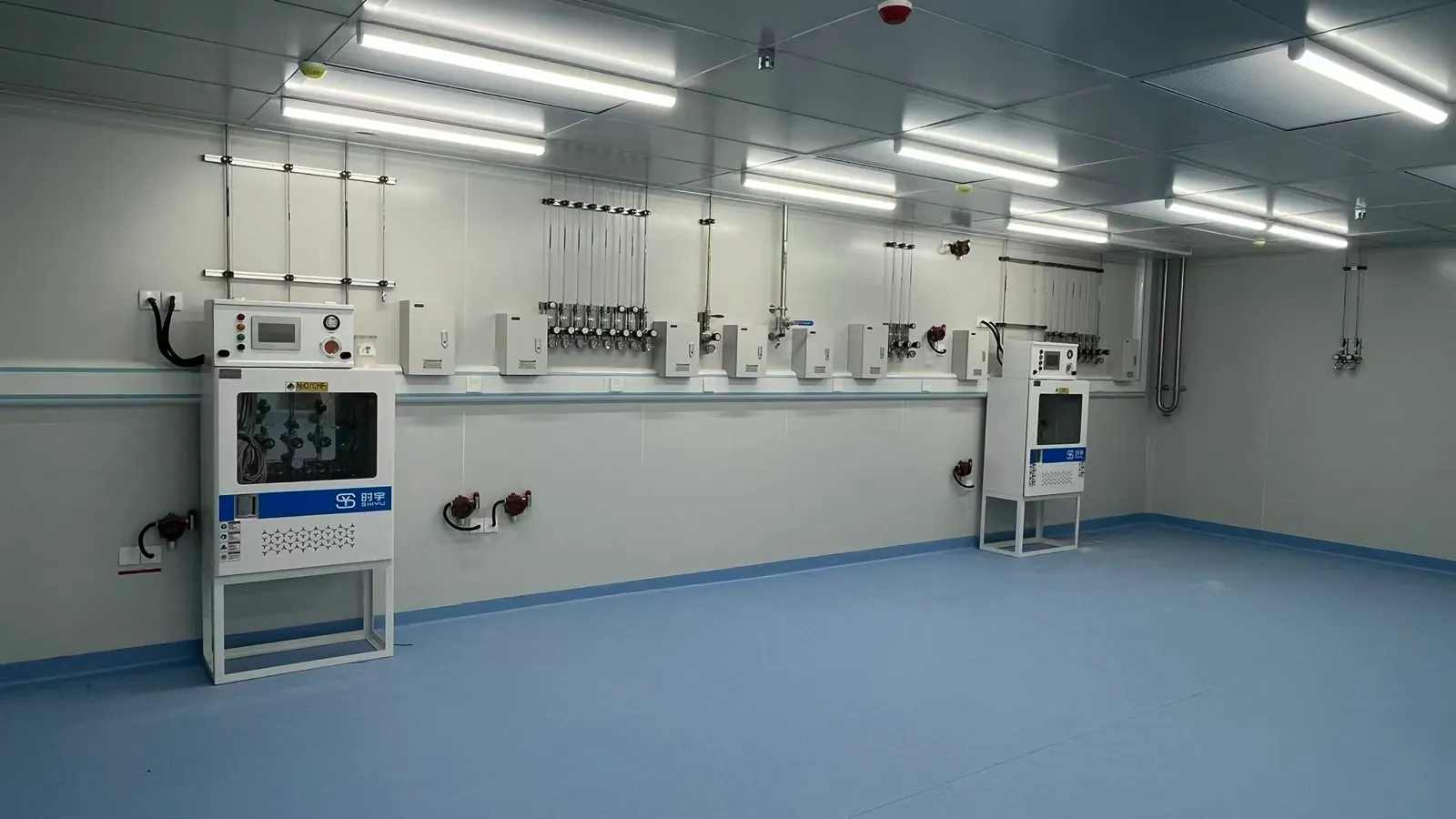
A completed pipeline is not ready for use until the source, regulators, isolation logic and outlet identity have been verified. Check that each point-of-use connection delivers the correct gas and operating pressure under the agreed conditions. Where alarms, cabinets or emergency isolation are fitted, demonstrate interfaces with the facility team before handover. The laboratory owner should know which tests establish installation acceptance and which instrument checks are still required.
Temporary hoses or fittings used in commissioning must be removed or documented as part of the final configuration. The return-to-service process should identify who authorizes the first cylinder connection, who checks the outlet and who accepts the instrument interface. This is especially important in a retrofit with active research rooms.
06 / RECORDS AND CHANGE
Leave a system the next technician can understand
The handover set should include approved and as-built drawings, a gas and outlet schedule, source equipment information, valve and line tags, material or joint records required by the project, inspection and test results, and operating instructions. The records should show where a branch can be isolated and what needs retesting after modification. Digital files should have a revision and a responsible owner.
Installation standards for laboratory gas piping vary by jurisdiction and application. If the project invokes NFPA, ASME, a university specification or a local code, the design team should record the relevant edition and requirements in the project documents. Avoid claiming that a photograph or generic guide proves compliance with a particular standard.
NEXT-STEP CHECKLIST
Installation package to confirm before work starts
- Approved gas list, instrument schedule and source-to-outlet drawings.
- Material, joining, clean handling and labeling requirements for each line.
- Site access, shutdown and occupied-room protection plan.
- Inspection boundaries, leak-test methods and acceptance limits.
- Commissioning roles for source, alarm and instrument interfaces.
- As-built, test and operating records required at handover.
PRACTICAL QUESTIONS
Installation planning questions
Which installation standard applies to every laboratory gas line?
There is no single worldwide answer. The gas, use, jurisdiction and facility specification determine the applicable code set. The project engineer should document the editions and clauses used.
When should concealed lines be documented?
Before a ceiling, wall or floor closes the route. Record the line identity, supports, connections, penetrations and location, then update the as-built drawings.
Is a pressure test enough for a high-purity service?
Not necessarily. Leak-tightness, cleanliness, purge or delivered gas quality may also matter. The agreed acceptance plan should state which checks apply and their limits.
Can an old line be reused during a renovation?
Only after its identity, material, condition, rating, cleanliness and suitability for the new service have been verified and approved.
LGF LABORATORY GAS SUPPORT
Bring the gas list and route plan to the installation review.
LGF can discuss the component and distribution information needed to turn an approved design into a traceable installation and handover package.