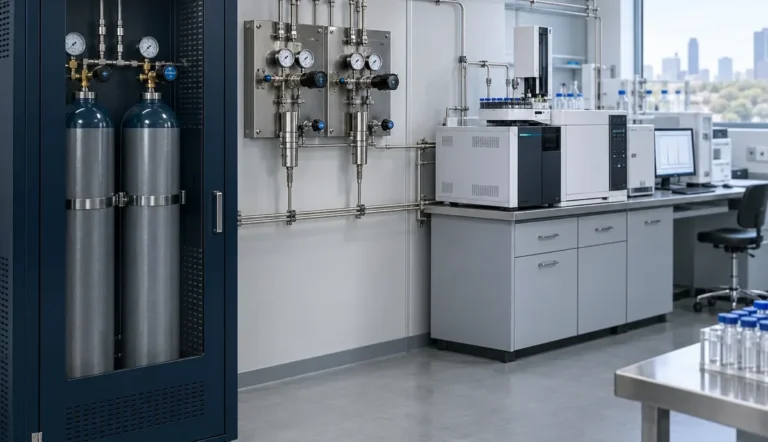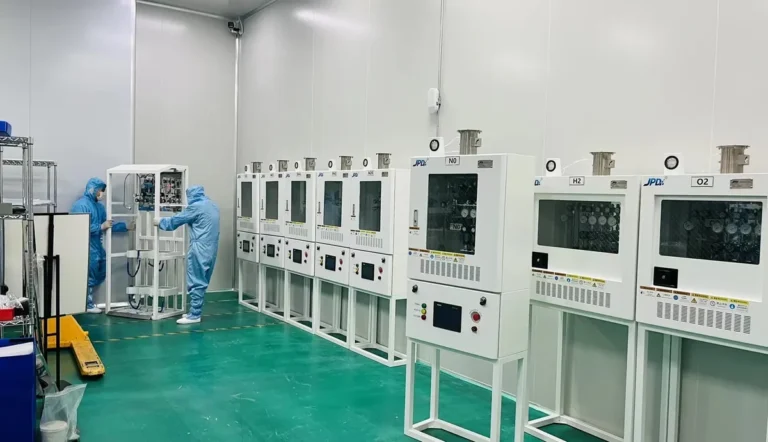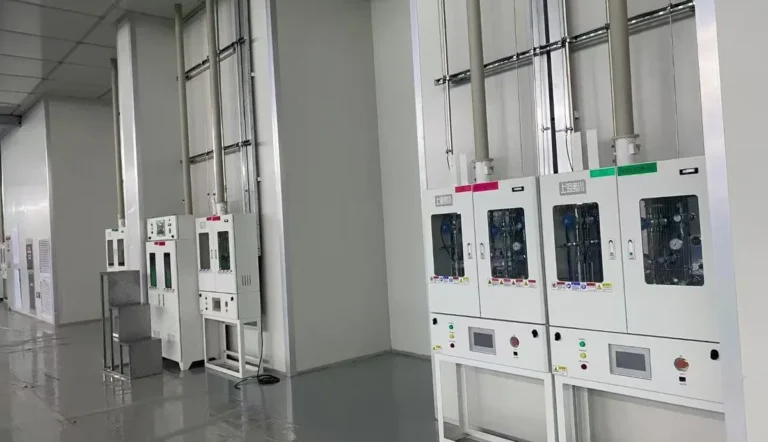

Quick answer: Choose a two-stage gas regulator when a high-pressure cylinder directly supplies a laboratory instrument that needs stable inlet pressure throughout a long or unattended run. Choose a single-stage regulator when the inlet pressure is already stable, the operating period is short, manual readjustment is acceptable, the required outlet pressure is unusually high, or the regulator is one stage within a larger pressure-control system. The number of stages is important, but it does not replace correct gas compatibility, purity, pressure range, flow capacity, connections, relief protection, and commissioning.
The practical decision is not simply “single-stage is cheaper” versus “two-stage is better.” A regulator must control two different disturbances: changing source pressure and changing gas flow. A two-stage design usually controls cylinder-pressure decay better, while the actual flow performance still depends on the regulator’s internal design, selected pressure range, valve coefficient, and operating point. Laboratory buyers should therefore select a regulator from the instrument requirement backward, not from a product photograph or gauge count.
Single-Stage vs. Two-Stage Gas Regulators at a Glance
| Selection factor | Single-stage regulator | Two-stage regulator |
|---|---|---|
| Pressure reduction | Reduces source pressure to delivery pressure in one regulating step | Reduces pressure to an intermediate level, then to final delivery pressure |
| Response as a cylinder empties | Outlet pressure may rise and require readjustment | Second stage largely compensates for the first stage’s inlet-pressure change |
| Best source condition | Stable pipeline, generator, liquid source vapor outlet, or short cylinder use | High-pressure cylinder with a large pressure change from full to empty |
| Best operating pattern | Supervised, intermittent, or noncritical service | Long, sensitive, continuous, or unattended instrument runs |
| Size and internal volume | Usually smaller, lighter, and easier to purge | Usually larger, heavier, and higher in internal volume |
| Purchase and maintenance | Lower initial cost and fewer internal parts | Higher initial cost and more components to inspect or service |
| Typical laboratory role | Point-of-use line regulator, utility gas, or first/second stage in a distributed system | Cylinder-mounted supply for analytical instruments and stable low-pressure service |
A two-stage regulator is usually the safer default for sensitive instrumentation supplied directly from a compressed-gas cylinder, but “two-stage” is not a complete specification. A poorly sized or incompatible two-stage regulator can deliver worse results than a correctly engineered single-stage arrangement. The final choice must be checked against the instrument manufacturer’s required inlet pressure, maximum flow, gas purity, and permissible pressure variation.
How Does a Single-Stage Gas Regulator Work?
A single-stage gas regulator balances the outlet-pressure force acting on a diaphragm against an adjustable spring force. When downstream demand lowers the outlet pressure, the diaphragm moves and opens the internal valve so that more gas enters. When the set pressure is restored, the diaphragm moves the valve toward closed. The regulator continuously repeats this mechanical balancing action while gas flows.
Single-stage regulation means that the full pressure reduction occurs across one valve-and-diaphragm mechanism. A cylinder may begin near its full rated pressure and end close to the minimum usable pressure, so the force applied by the inlet gas changes substantially during use. In many conventional regulator designs, falling inlet pressure causes the outlet pressure to rise. This behavior is called supply pressure effect, decaying inlet characteristic, or inlet pressure dependency.
How Does a Two-Stage Gas Regulator Work?
A two-stage gas regulator places two regulating mechanisms in series inside one assembly. The first stage reduces the high and changing cylinder pressure to a lower intermediate pressure. The second stage receives that controlled intermediate pressure and reduces it again to the user-selected delivery pressure. Each stage has its own diaphragm, spring, seat, and valve mechanism.
The second stage sees a much smaller inlet-pressure change than a single cylinder-mounted stage would see. When the cylinder pressure falls, supply pressure effect in the first stage changes the intermediate pressure; the second stage then attenuates most of that change before gas reaches the instrument. A university regulator guide therefore recommends dual-stage regulation for analytical instruments where constant delivery pressure is critical. See the laboratory regulator selection guide for the underlying operating diagrams and material considerations.
What Is Supply Pressure Effect, and Why Does It Matter?
Supply pressure effect is the change in regulator outlet pressure caused by a change in inlet pressure while flow conditions are otherwise comparable. It is commonly expressed as a delivery-pressure change for a specified inlet-pressure change. In a typical unbalanced single-stage cylinder regulator, outlet pressure rises as cylinder pressure falls. The instrument therefore receives a different pressure near the end of the cylinder than it received when the cylinder was full.
Supply pressure effect matters when an instrument uses inlet pressure as part of its own control range. A gas chromatograph, calibration system, controlled-atmosphere chamber, flame instrument, or low-flow reactor may have internal valves or mass-flow controls that assume the upstream supply remains within a defined band. Excessive outlet rise can alter flow, reduce control margin, trigger an alarm, or expose a downstream component to pressure above its intended normal condition.
How Are Droop, Creep, and Supply Pressure Effect Different?
Droop is a reduction in outlet pressure as gas flow increases. A regulator may be set correctly at no flow but deliver a lower pressure when the instrument begins consuming gas. Droop is evaluated with a flow curve and depends on spring design, diaphragm area, valve geometry, pressure range, and operating point. A regulator selected far outside the required flow range may provide poor control even when its maximum flow rating looks generous.
Creep is a gradual rise in outlet pressure when downstream flow is stopped and the regulator should be closed. Creep usually indicates that the seat is not sealing because of contamination, wear, damage, or incompatible material. Creep is not a normal consequence of choosing one stage instead of two. A regulator that creeps should be isolated and evaluated under the laboratory’s safety procedure rather than repeatedly adjusted.
Supply pressure effect is an outlet change caused by changing inlet pressure. It becomes especially visible while a high-pressure cylinder empties. These three effects require different corrective actions: choose a suitable stage arrangement for supply pressure effect, size the regulator and pressure range correctly for droop, and remove a regulator with persistent creep from service.
Which Regulator Fits Common Laboratory Instruments?
| Instrument or service | Typical selection direction | Reason and qualification |
|---|---|---|
| Gas chromatograph carrier or detector gas from a cylinder | Two-stage | Long sequences and internal flow controls benefit from stable source pressure; always follow the instrument site-preparation pressure |
| ICP-OES or ICP-MS argon | Two-stage or engineered central two-step regulation | Demand can be relatively high and sustained; verify flow curve as carefully as pressure stability |
| Atomic absorption fuel and oxidant gases | Two-stage for direct cylinder supply | Stable flame conditions require controlled pressure; gas-specific safety and flashback controls remain separate requirements |
| Calibration gas or span gas | Application dependent | Two-stage supports long controlled delivery; low-dead-volume single-stage designs may suit small cylinders and short sampling if pressure drift is acceptable |
| Incubator carbon dioxide | Often two-stage for a high-pressure cylinder | Stable low delivery pressure helps the instrument valve operate consistently; liquid withdrawal and source phase require separate review |
| Glovebox or controlled-atmosphere chamber | Two-stage or source regulator plus point-of-use regulator | Stable pressure improves purge and makeup-gas control, especially during unattended operation |
| Utility nitrogen, air, or argon from a stable building line | Single-stage line regulator | Upstream pressure is already regulated, so local final pressure control is usually the main task |
| Short supervised purge or blowdown | Single-stage may be sufficient | Manual monitoring is practical, provided the gas, pressure, flow, and downstream rating are compatible |
Instrument tables are only a starting point. The instrument manufacturer defines the acceptable inlet pressure and flow, while the laboratory defines purity, source arrangement, runtime, hazard controls, and maintenance method. For example, two instruments with the same gas may need different regulators because one runs continuously at low flow while the other draws a high transient flow during ignition or purge.
Gas chromatography deserves special attention because a modern instrument may contain its own electronic pressure or flow controller. The external regulator must still maintain enough pressure above the instrument’s maximum operating requirement for the internal controller to function. A chromatography engineering article explains how droop and supply pressure effect reach the instrument and why dual-stage regulation is commonly preferred for cylinder supply. See the gas cylinder setup and regulator analysis for a detailed technical discussion.
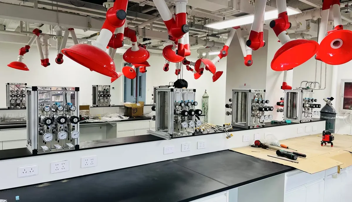
When Is Each Regulator Type the Better Choice?
A single-stage regulator is the better choice when gas arrives from a stable pipeline or upstream-regulated manifold, when work is short and supervised, or when a specialized requirement such as high delivery pressure, high flow, or low internal volume favors a suitable single-stage design. A two-stage regulator is worth the extra cost when a high-pressure cylinder must support long, sensitive, or unattended operation without manual readjustment. The economic comparison should include lost samples, interrupted experiments, troubleshooting time, and downstream risk rather than purchase price alone.
Neither choice removes the need for pressure monitoring and overpressure protection. A regulator controls pressure during normal operation; relief devices, shutoff valves, downstream ratings, alarms, and safe vent routing must address credible failures in the complete system.
How Do Purity and Gas Compatibility Change the Decision?
Stage count does not determine whether a regulator is suitable for a gas. Wetted body material, diaphragm, seat, seals, lubricants, cleaning process, internal surface condition, leak integrity, and connection all affect compatibility and purity. A brass body may be economical for compatible noncorrosive gases, while stainless-steel barstock construction is commonly selected for high-purity, reactive, or corrosive service after a gas-specific compatibility review.
A metal diaphragm and metal-to-metal diaphragm seal reduce permeation, outgassing, and atmospheric contamination compared with many elastomeric constructions. Low internal volume and a controlled purge path matter for trace analysis and calibration mixtures because retained gas delays composition changes. Moisture-sensitive or corrosive gases require materials and procedures that prevent reaction products and seat damage.
Oxygen service requires dedicated compatibility and cleanliness controls. Components must be specified, cleaned, assembled, and maintained for the oxygen concentration and pressure. A regulator previously used for another gas should not be reassigned merely because an adapter can connect it. Gas-specific inlet connections are safety controls, and adapters can defeat their purpose.
For a broader method of matching gas hazard, purity, source, pipeline, and point-of-use equipment, see LGF’s laboratory gas delivery system selection workflow. Laboratories managing analytical-grade and calibration gases can also use the specialty gas management guide for analytical labs to connect regulator selection with certificates, changeover, storage, and contamination control.
How Should Pressure Range and Flow Capacity Be Specified?
The regulator inlet rating must exceed the maximum credible source pressure at the highest expected temperature. The delivery range should place the normal set point in a controllable portion of the regulator’s range rather than near its maximum. Choosing a 0-20 bar regulator for an instrument that normally requires 1 bar may make fine adjustment difficult even though the nameplate range technically includes the set point.
Flow selection must use the peak simultaneous demand, not only average consumption. Purge cycles, ignition, instrument standby-to-run transitions, and multiple instruments on one branch can create short high-flow conditions. Request a flow curve at representative inlet and outlet pressures. The curve reveals droop and usable control range more reliably than a maximum flow number measured under a different condition.
The system pressure-drop calculation must include the regulator, valves, filters, excess-flow devices, flexible connections, piping length, fittings, elevation where relevant, and the instrument connection. A correctly sized regulator cannot compensate for an undersized distribution line. Conversely, an oversized high-flow regulator may have poor resolution and may make downstream relief sizing more demanding.
Integral Two-Stage or Two Separate Regulators?
An integral two-stage regulator is usually convenient for one cylinder feeding one nearby instrument. Both pressure reductions occur in one assembly, installation is compact, and the operator adjusts one final set point. The tradeoffs are a larger package, more internal volume than a comparable single stage, and replacement of the complete assembly when either stage requires service.
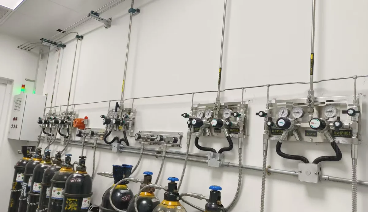
Two separate regulators are often better for a centralized laboratory gas system. A source-side regulator or laboratory gas manifold reduces cylinder pressure for the building distribution line. A second line regulator near the instrument establishes the final delivery pressure. This architecture isolates distribution pressure from instrument pressure and lets different branches serve instruments with different requirements.
Separate stages must be engineered as one system. The first-stage outlet must remain above the second stage’s required inlet across peak flow and source changeover. The distribution line and components must be rated for the intermediate pressure. Relief protection must account for the maximum pressure that could reach each downstream section if a regulator seat fails.
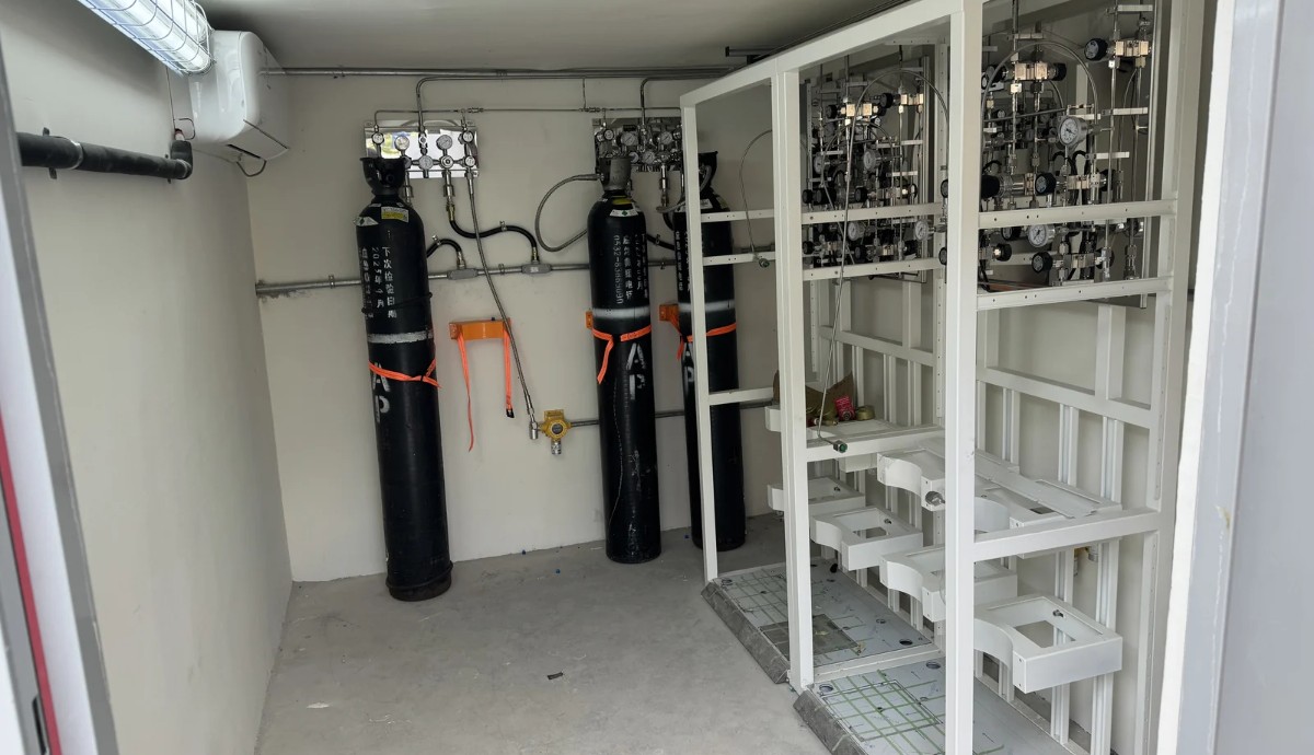
What Safety Features and Connections Should Buyers Check?
A regulator specification should identify the exact gas and cylinder connection standard for the project location. The inlet connection must match the authorized source without improvised adapters. The outlet connection must match the downstream tubing or hose pressure rating and cleanliness requirement. Gauge ranges, gauge materials, pressure units, orientation, panel mounting, and valve configuration should be stated rather than assumed.
The required safety features depend on the gas and system. Possible requirements include a captured bonnet vent, relief valve or dedicated relief path, outlet isolation, purge connection, check valve, excess-flow protection, pressure switch or transducer, and enclosure ventilation. A relief valve built into a regulator may protect only a limited internal volume and may not satisfy downstream system relief requirements.
A national laboratory gas-safety guide lists stage count, inlet and outlet ranges, flow, materials, and fittings as separate regulator selection factors. That separation is useful because selecting two stages does not resolve the other specifications. Review the laboratory gas safety and regulator guidance, then apply the current rules and authority having jurisdiction for the actual facility.
LGF’s laboratory gas equipment safety standards guide explains how equipment requirements should be converted into testable purchasing clauses and documentation. Regulatory and code compliance must be confirmed for the installation location; a component catalogue statement alone is not an installation approval.
How Should a Regulator Be Commissioned?
- Verify the specification: confirm gas service, connections, pressure ranges, materials, flow rating, orientation, and traceability.
- Inspect and install correctly: check sealing surfaces and gauges, use the approved gas-specific connection, and avoid unauthorized adapters, lubricants, or sealants.
- Pressurize and leak-test safely: unload the adjustment mechanism, open the source slowly, and test the defined high- and low-pressure boundaries with a compatible method.
- Test under realistic demand: set pressure while gas flows and record delivery stability at representative inlet pressures and peak flow when performance is critical.
- Verify protection and handover: test isolation, relief, alarms, and vent paths, then retain certificates, set points, test records, spares, and the authorized changeout procedure.
How Can Regulator Problems Be Diagnosed?
| Observed symptom | Likely engineering question | Recommended response |
|---|---|---|
| Outlet pressure rises as the cylinder empties | Is supply pressure effect too large for a single-stage regulator? | Compare measured change with the instrument tolerance; consider two-stage or distributed two-step regulation |
| Outlet pressure falls when flow begins | Is the regulator or upstream path undersized, or is the selected range unsuitable? | Check the flow curve and total system pressure drop at peak demand |
| Outlet pressure rises with the downstream valve closed | Is the seat leaking or contaminated? | Isolate and remove the regulator from service under the approved procedure |
| Pressure oscillates or hunts | Is the regulator interacting with a downstream controller, oversized valve, or changing demand? | Review control volumes, set points, flow curve, and instrument inlet requirements |
| Analyzer baseline or calibration changes after cylinder replacement | Did air enter, was the purge incomplete, or are wetted materials contaminating the gas? | Review changeout, purge, leak integrity, dead volume, materials, and gas certificate |
| Gauge does not return to zero | Has the gauge been damaged or overpressurized? | Tag the assembly out of service and have it evaluated by qualified personnel |
Troubleshooting should separate normal regulator behavior from unsafe failure. Supply pressure effect and droop can be characterized with operating data; persistent creep, damaged gauges, external leakage, incompatible materials, or uncontrolled pressure are reasons to stop using the assembly. Do not compensate for a defective regulator by repeatedly changing the set point.
What Should Be Included in a B2B Regulator RFQ?
A useful request for quotation should make performance verifiable. Include the following information for every regulator service:
- gas name, composition, concentration, purity grade, and moisture or oxygen sensitivity
- source type, nominal pressure, maximum credible inlet pressure, and minimum changeout pressure
- required normal outlet pressure, allowable adjustment range, and maximum permissible outlet pressure
- average, minimum, peak, and purge flow, including the number of simultaneous instruments
- single-stage, integral two-stage, or separate two-step architecture and the reason for that choice
- maximum acceptable supply pressure effect and droop at defined test conditions
- body, diaphragm, seat, seals, surface condition, cleaning, and leak-rate requirements
- inlet and outlet connection standards, port orientation, mounting method, and gauge units
- relief, vent, purge, isolation, alarm, and enclosure interface requirements
- applicable regulations, standards, documentation, test certificates, spare parts, and warranty
Comparable quotations require the same design basis. If one supplier assumes a stable pipeline source while another assumes direct cylinder pressure, their proposed regulator stages and prices are not comparable. The RFQ should therefore include a simple flow diagram showing the source, regulator stages, distribution pressure, point-of-use control, and instrument interface.
Final Selection Rule
For a high-pressure cylinder feeding a pressure-sensitive laboratory instrument, specify two-stage regulation unless a documented analysis supports another arrangement. For a stable pipeline or an already regulated source, a single-stage point-of-use regulator is often the correct and simpler solution. For a centralized gas system, one source regulator plus one instrument-side line regulator can provide two-step control without requiring an integral two-stage unit at every point.
The final purchase decision must satisfy six questions at the same time: Is the regulator compatible with the gas? Does it preserve the required purity? Can it withstand the maximum inlet pressure? Does it hold the required outlet pressure across source decay and changing flow? Can it deliver peak demand? Does the complete system provide the necessary isolation, relief, venting, and documentation? A regulator that fails any one of these checks is not suitable, regardless of stage count.
Frequently Asked Questions
Is a two-stage regulator the same as a two-gauge regulator?
No. Two gauges normally show inlet pressure and outlet pressure, while two stages describe two separate pressure-reducing mechanisms. A single-stage regulator can have two gauges, and a two-stage regulator may also have two gauges. Stage count must be confirmed from the model specification or internal design, not from the number of gauges.
Can two single-stage regulators replace one two-stage regulator?
Yes, when the two regulators are engineered in series with a suitable intermediate pressure, component ratings, relief protection, and flow capacity. This arrangement is common in central gas systems where the first regulator is at the source and the second is near the instrument.
Does a two-stage regulator guarantee constant gas flow?
No. A regulator controls pressure, while flow depends on downstream resistance and control devices. Two-stage regulation reduces outlet change caused by inlet-pressure decay, but flow can still change because of droop, instrument valves, tubing restrictions, or process demand. Use a suitable flow controller when the method requires controlled flow.
Should every gas chromatograph use a two-stage cylinder regulator?
Two-stage regulation is commonly appropriate for a gas chromatograph supplied directly from a high-pressure cylinder, especially for long sequences. The final requirement must come from the instrument’s site-preparation documentation, including required inlet pressure, pressure margin, gas grade, and peak demand.
Discuss Your Laboratory Gas Pressure-Control Project
LGF Lab Gas Flow supports B2B laboratory gas projects with source manifolds, high-purity gas regulators, point-of-use pressure-control panels, gas cabinets, valves, stainless-steel piping, monitoring, testing, and system integration. A useful project review begins with your gas list, cylinder or central source, purity, inlet and outlet pressures, peak flow, instrument models, runtime, continuity target, layout, and required standards.
Contact LGF Lab Gas Flow for a regulator and laboratory gas system review, or explore the website for more information about high-purity laboratory gas regulators, gas manifolds, point-of-use systems, and complete gas delivery solutions.