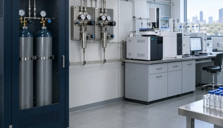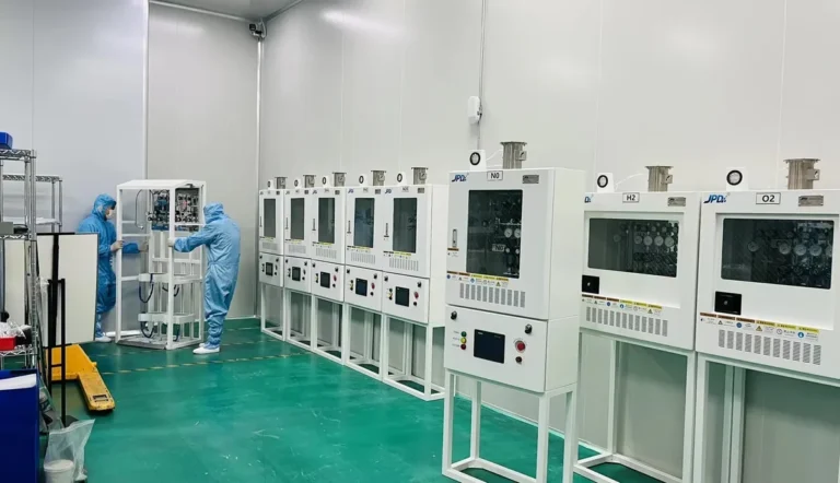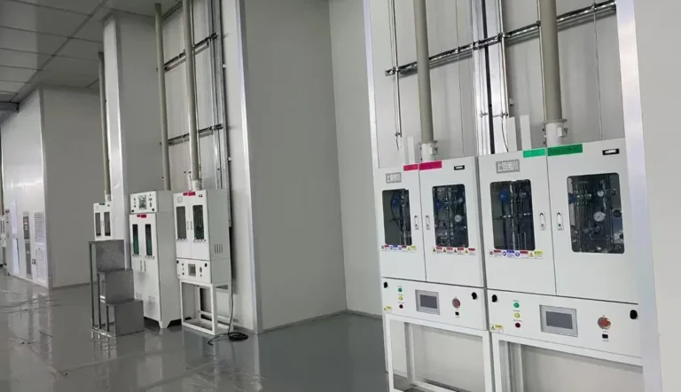

Laboratory gas delivery systems move a specified gas from a cylinder, bulk source, or generator to an instrument at the required purity, pressure, and flow. A complete system includes source control, compatible components, distribution piping, point-of-use outlets, monitoring, and documented handover. The best configuration depends on the gas hazard, the instrument demand, the laboratory layout, and how the facility will maintain the system.
Estimated reading time: 13 minutes. This guide is for laboratory managers, facilities teams, engineering consultants, and B2B buyers who need to compare options and prepare a useful project brief.
What does a laboratory gas delivery system actually include?
A laboratory gas delivery system is the entire controlled path between gas supply and end use. The gas source may be a cylinder, a cylinder bank, a bulk installation, or an on-site generator. A source assembly typically provides isolation, pressure regulation, and an appropriate changeover method when continuous supply is required. Tubing and valves then carry the gas to clearly identified outlets or instrument connections.
The delivery path is only one part of the design. A laboratory gas system may also need gas cabinets, local exhaust, leak detection, alarms, emergency isolation, purge arrangements, or exhaust treatment, depending on the gas and the local risk assessment. These controls must be selected for a defined hazard, rather than added as a generic accessory list.
A useful starting point is a gas-use schedule. For every service, the schedule should identify the gas composition, grade, hazards, source type, cylinder connection, required outlet pressure, expected normal and peak flow, number of simultaneous users, and intended instrument. A missing value becomes a design assumption; an incorrect assumption can cause pressure instability, contamination, or an unsafe installation.
How does gas travel from the source to the instrument?
The usual sequence is source, primary isolation, source pressure control, distribution line, branch isolation, point-of-use control, and instrument connection. A changeover manifold can keep a service available while a depleted cylinder bank is replaced. A gas cabinet or ventilated enclosure may be needed where the hazard assessment requires containment and monitored extraction.
Pressure should be considered along the full route. A source regulator reduces high cylinder pressure to a controlled distribution pressure, while a point-of-use regulator may provide a lower and more stable pressure for a sensitive instrument. A gauge at the source does not prove that a distant instrument receives enough pressure under peak flow; losses through tubing, fittings, filters, and simultaneous demand must be considered.
Gas quality also changes along the route if the system is poorly specified. An appropriate source grade can still be compromised by incompatible wetted materials, permeable seals, trapped dead legs, moisture ingress, or an unclean connection. The design therefore needs a gas-quality target at the instrument, not only a purity claim on the cylinder label.
When should a laboratory choose a local cylinder or a central supply?
A local cylinder can be practical for one instrument with infrequent use, a short connection, and limited demand. It is usually easier to establish than a building-wide network, but cylinder changes take place near laboratory activity and each instrument may need its own regulator and management routine. Local supply is a configuration choice, not a substitute for the required cylinder controls.
A centralized supply serves multiple outlets from a controlled source location. It can simplify cylinder management and keep source equipment away from workstations, but the system needs careful route planning, demand sizing, identification, isolation, and coordinated commissioning. A central system is most valuable when several users need the same gas or when uninterrupted supply is operationally important. LGF’s centralized laboratory gas supply overview explains the source-to-outlet architecture in more detail.
| Decision factor | Local cylinder | Centralized distribution |
|---|---|---|
| Typical demand | One or a few nearby instruments | Multiple rooms or repeated outlets |
| Source changes | At or near each instrument | At a managed source area |
| Initial coordination | Limited route planning | Higher design and building coordination |
| Continuity | Depends on local change procedure | Can incorporate monitored bank changeover |
| Expansion | Adds more local source points | Requires planned capacity and branches |
The right choice is determined by total demand, risk, operating cost, and future changes rather than by an outlet count alone. A compact research laboratory may benefit from a small, controlled system; a multi-room testing facility may need centralized distribution. The compact research laboratory supply approach shows how a smaller project can be scoped without copying a large-campus layout.
Which components have the greatest effect on performance?
The regulator establishes the pressure behavior that the instrument sees. Regulator selection should reflect inlet-pressure range, desired outlet range, flow, gas compatibility, required cleanliness, and acceptable pressure variation as the source empties. A regulator that fits the connection but cannot meet the dynamic flow condition is not an adequate match.
The manifold determines how one or more sources are connected and isolated. A manual changeover may suit a noncritical service with planned interruptions; an automatic or monitored changeover may be appropriate where interruption has a high process cost. The choice should state what happens during bank depletion, how operators are alerted, and whether the changeover introduces an unacceptable pressure dip.
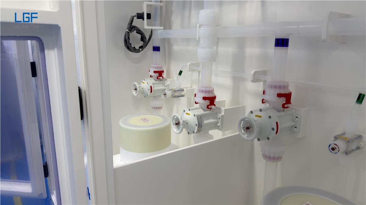
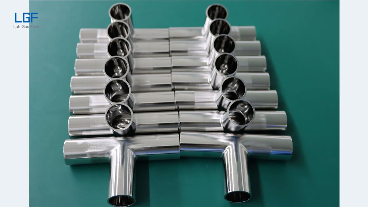
The tubing and fittings form the contamination and leakage boundary. Material, internal finish, joint type, cleaning method, and handling procedure should match the gas and analytical requirement. Stainless steel is often considered for high-purity distribution, but its grade and preparation still need to be specified. The laboratory gas piping design guide covers the route and interface decisions that make the equipment work as one system.
The point-of-use assembly is the final control before an instrument. It may include a local shutoff, regulator, gauge, filter, check feature, or connection arrangement, according to service requirements. A clear outlet label and a documented interface prevent an otherwise well-designed pipeline from ending in an ambiguous connection.
How should pressure, flow, and pipe size be specified?
Pressure, flow, and pipe size are linked design variables. The instrument manufacturer defines the usable inlet pressure and consumption range; the engineer then accounts for line length, elevation where relevant, fittings, simultaneous users, and allowable pressure drop. Choosing a tube diameter from a catalog before defining peak demand can lead to excessive loss or needless material cost.
The most useful flow value is the simultaneous design case, not a sum of every instrument’s nameplate maximum unless all will operate together. A gas-use schedule should distinguish normal flow, short peaks, purge flow where applicable, and planned expansion. The pressure budget should show the minimum source condition and the minimum acceptable pressure at the most demanding outlet.
Oversizing is not always harmless. Large internal volume can increase purge time and gas use, particularly for expensive high-purity gases. Undersizing can cause pressure drops and unstable instrument operation. The procurement specification should therefore give performance at the outlet and the design assumptions used to reach it, rather than simply prescribing the largest available tube.
How do purity and material compatibility change the design?
Purity requirements start with the analytical method and instrument, not a general label such as “laboratory grade.” A calibration gas, carrier gas, inert purge gas, and reactive process gas may have different limits for moisture, oxygen, particles, or trace contaminants. The intended measurement or process determines which impurities matter and where a final filter or purifier may be justified.
Material compatibility is a separate question. Gas-contacting metals, seals, diaphragms, lubricants, and connection components must be suitable for the specific gas and operating conditions. A component that works with inert gas should not automatically be reused for an oxidizing, corrosive, flammable, or toxic service. The corrosive and high-purity specialty gas supply page describes why the gas identity changes the source and distribution strategy.
Cleanliness must be protected through procurement and construction. A cleaned tube can lose its intended condition if it is stored uncapped, cut with unsuitable tools, or joined without a controlled procedure. A high-purity project should state the cleanliness and packaging expectations, installation controls, purge method, and acceptance checks in the purchase package.
What changes when the gas is flammable, toxic, corrosive, or an asphyxiant?
A hazardous gas needs a design based on its particular release scenario. Flammable gas may call for controls addressing ignition and accumulation; toxic or corrosive gas may call for containment, detection, exhaust, and compatible materials; inert gas can still create an oxygen-deficiency risk in an enclosed space. The hazard review must consider source storage, distribution, occupied spaces, maintenance, and credible leak points.
Safety systems should be tied to an action. A gas detector, alarm, or emergency shutoff has little value unless the triggering condition, response, responsible operator, and reset procedure are defined. Ventilation and exhaust should be engineered with the building systems; they are not automatically interchangeable with a gas cabinet or a leak detector.
The applicable code and authority requirements vary by location, gas quantity, occupancy, and installation type. A qualified engineer and the site’s environmental, health, and safety team should approve the hazard analysis and final design. In the United States, OSHA’s compressed-gas requirements provide a regulatory starting point for cylinder handling, but local fire, building, and laboratory requirements may also apply. LGF’s flammable laboratory gas supply overview provides an example of a service that requires a dedicated safety concept.
How should the piping route and outlets be planned?
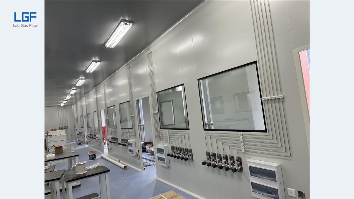
A good pipe route stays understandable after the laboratory is occupied. The design should identify the gas on drawings and at accessible locations, separate incompatible services as required, allow safe maintenance access, and avoid hidden connection points that cannot be inspected. The route should also account for other trades, equipment moves, and the location of future branches.
Every outlet should have a defined destination and connection. The project schedule should name the room, instrument, gas, outlet pressure, flow, connection type, and required isolation point. A generic “gas point” on a drawing leaves too much room for a wrong connection or an unsuitable regulator at commissioning.
Expansion should be planned as a controlled change. Spare capacity, capped branches, and accessible isolation can make future work easier, but unused connections should be identified and kept secure. A future outlet is not safe to energize merely because a tee was included during the original installation.
What should be verified during installation and commissioning?
Installation begins with an approved design and a component check. Each delivered part should match the specified service, pressure class, material, connection, and cleanliness level. Changes made in the field should be recorded and reviewed before they become concealed by walls or ceilings.
Commissioning should demonstrate that each line is correctly identified, sufficiently tight for its service, clean where required, and functional at the intended operating conditions. The test method, medium, pressure, duration, and acceptance criteria must be defined by the qualified project team for the specific gas and system. A single generic pressure test cannot prove purity, correct outlet identity, or alarm behavior.
The handover package should include as-built drawings, component data, gas and outlet schedules, test records, alarm and isolation logic, operating instructions, and maintenance tasks. Without those records, a system can appear complete while leaving operators unable to diagnose a fault or plan a safe modification. LGF’s pipeline installation guide outlines the controlled sequence from material handling to handover.
How should operators maintain reliability after handover?
Routine management begins with knowing the service. Operators should be able to identify the gas, source bank, normal pressure range, low-supply alarm, isolation location, and instruments served. A changeover procedure should be written for the installed equipment and performed by trained personnel; the procedure should not be inferred from another gas service.
Inspection frequency depends on the gas, service duty, equipment instructions, local requirements, and the site’s risk assessment. Records should capture abnormalities such as pressure drift, repeat alarms, unusual consumption, damaged tubing support, and failed detection checks. Trend information can reveal a developing leak or capacity problem before an instrument fails.
Any laboratory renovation should trigger a review of the gas-use schedule and as-built drawings. A new instrument can change flow and pressure requirements for every outlet on a shared line. An outlet relocation can also alter the safety analysis if the new area has different ventilation or occupancy conditions. LGF describes the maintenance and documentation scope on its after-sales maintenance and annual inspection page.
How do different laboratory applications affect system design?
An analytical testing laboratory often prioritizes stable carrier gas, repeatable pressure, and trace-contamination control. A research laboratory may need greater flexibility because instruments and gas types change frequently. A biopharmaceutical laboratory may emphasize controlled documentation and cleanable or validated interfaces for a defined process. These are design tendencies, not a fixed specification for every facility.
A university facility commonly has many users and changing experiments, so outlet identification, isolation, training, and change control are especially important. A pilot process with reactive gas may have fewer outlets but a more demanding hazard analysis. Application-specific examples can help scope a project; LGF’s laboratory gas supply application pages cover several operating contexts.
The project brief should separate “must have” performance from possible future uses. Trying to make every line suitable for every hypothetical gas raises cost and can obscure real risks. A defined service matrix, with a controlled process for later changes, usually produces clearer engineering and procurement decisions.
What should a B2B buyer put in a quotation request?
A useful request for quotation includes a gas list with composition, purity and hazards; source and cylinder details; instrument quantities; pressure and flow at each outlet; line lengths and building drawings; required control and alarm interfaces; and expected expansion. It should also identify the site location so suppliers can account for applicable approvals and project coordination.
Ask bidders to state their scope boundaries. A component quotation, a fabricated manifold package, a complete installed network, and a commissioned turnkey system are different deliverables. Each offer should clearly show what is included for engineering, materials, installation, tests, as-built records, training, and after-sales support.
Compare quotations by documented performance and service scope, not by unit price alone. A low equipment price may omit site coordination, compatible fittings, point-of-use regulators, alarms, or commissioning evidence. A fair comparison uses the same gas schedule and acceptance criteria for every bidder. LGF’s product selection guide can support component discussions before a formal quote.
How should lifecycle cost be compared?
The purchase price is one part of the laboratory gas delivery system cost. A full comparison includes cylinder handling time, routine inspection, replacement parts, gas losses during source changes or purging, downtime, and future modification. A central network may cost more to install but reduce repeated local cylinder work; a short local line may be economical when only one instrument uses the gas.
Lifecycle cost also depends on the quality of documentation. A clearly labeled branch and an accurate as-built drawing shorten fault finding and future extensions. A system without a usable equipment list can make a small repair expensive because the service team must first identify the installed components and their ratings.
For a quotation comparison, request an itemized scope and identify assumptions that could change after a site survey. The buyer should understand who owns the design, who supplies the cylinder connections, who coordinates with building ventilation, and who performs final tests. A transparent scope makes the lowest and highest offers easier to compare on the same technical basis.
Which questions should be answered before approving a design?
What gas reaches each instrument? The answer should identify composition, purity, normal and peak flow, required inlet pressure, and the exact outlet connection. This is more useful than a room-level list because two instruments in the same room may have different pressure or contamination limits.
Where can the gas be isolated? The answer should identify source, branch, and point-of-use isolation where required by the design. The locations must be accessible and labeled so an operator can act without tracing hidden piping during an abnormal event.
What happens if supply is depleted or an alarm activates? The answer should describe changeover, notification, shutdown behavior, and responsible response. A written sequence lets facilities staff test the system and train users against the actual installed logic.
How will the system be accepted? The answer should define the required records for identity, tightness, cleanliness or purity where applicable, regulator performance, alarm functions, and as-built documentation. Acceptance based only on visual completion leaves important failure modes untested.
Frequently asked questions
Is a laboratory gas delivery system the same as a gas pipeline?
A gas pipeline is the distribution portion of a laboratory gas delivery system. The complete system also includes the source, pressure control, isolation, outlets, monitoring, and documentation needed to deliver gas safely and consistently.
Does every laboratory need an automatic changeover manifold?
No. Automatic changeover is most useful when supply interruption is costly or difficult to manage. A low-demand service may use a simpler controlled arrangement if the risk assessment and operating plan support it.
Can the same tubing be used for every laboratory gas?
No. Tubing and all wetted components must be evaluated against the gas, pressure, purity target, and applicable requirements. Material compatibility and cleanliness cannot be assumed from tube size alone.
What is the first document needed for a new project?
A gas-use schedule is the best first document because it ties every gas to a source, instrument, pressure, flow, purity requirement, and hazard. The schedule becomes the basis for architecture, sizing, quotations, and acceptance checks.
Plan a laboratory gas delivery project with LGF
LGF Lab Gas Flow works with laboratory and facility teams on gas supply solutions, piping design, installation, and project support. For a B2B inquiry, share your gas list, floor plan, instrument schedule, outlet requirements, and target delivery scope. LGF can use those inputs to discuss a suitable source-to-instrument approach and a clearer quotation. Contact LGF about your laboratory gas project to start the technical conversation.