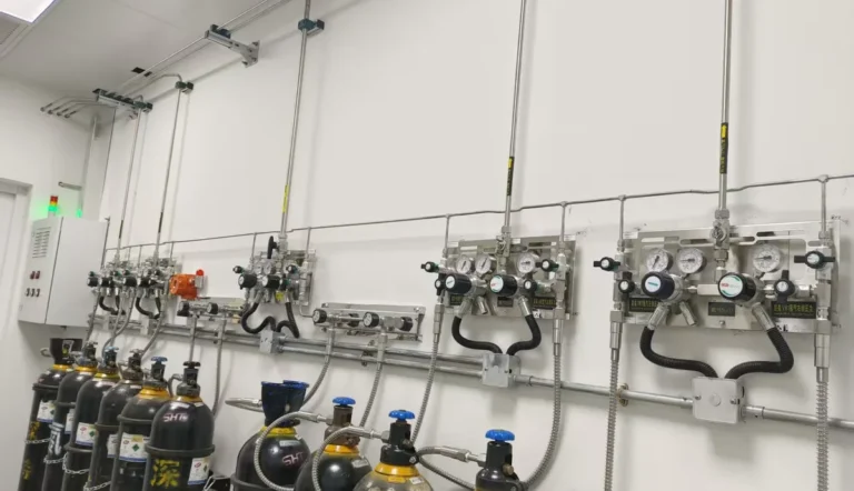

A laboratory gas manifold connects one or more cylinders of the same specified gas to a controlled supply path, then delivers gas at a pressure and flow suitable for the downstream system. The right manifold depends on the gas hazard, purity, peak demand, inlet pressure, reserve strategy, and how an operator changes cylinders. A dual-bank changeover manifold can reduce interruptions, but it cannot replace correct gas-specific connections, sound piping, alarms, or a documented operating procedure.
Reading time: 13 minutes. This guide treats the manifold as a source-side engineering and purchasing decision. It develops the manifold-specific questions that the broader laboratory gas delivery system overview introduces. The actual gas, installation, local rules, and approved design determine final specifications.
What is a laboratory gas manifold?
A laboratory gas manifold is the assembly that connects cylinder outlets or cylinder banks to a common regulated gas supply. A typical assembly may include gas-specific inlet connectors, flexible or rigid inlet lines, isolation valves, check valves where specified, gauges or transducers, regulators, purge connections, a changeover device, and an outlet to the distribution line. The exact component list changes with the gas and operating mode.
The manifold begins at the specified cylinder connection and ends at its defined outlet interface. It is not the entire delivery system: downstream piping, point-of-use regulators, outlets, instruments, ventilation, monitoring, and emergency controls remain separate design elements. A purchase order should identify that boundary so the manifold supplier and piping contractor do not each assume the other is providing an essential part.
A valve manifold box is related equipment but is not automatically a cylinder changeover manifold. A valve box may distribute, isolate, or monitor multiple branches after a gas source; a cylinder manifold manages source-side connections. The required function should appear on a process drawing rather than being inferred from the word “manifold” alone.
How does gas move through a cylinder manifold?
Gas leaves an approved cylinder through its gas-specific valve connection and enters an inlet line rated for the maximum source pressure. Isolation and monitoring points let operators identify the bank in service. A regulator or staged regulation arrangement reduces source pressure to a controlled outlet pressure before gas enters the distribution line.
A dual-bank assembly provides two source paths, commonly called duty and reserve. The changeover section selects the available path when the active bank falls below its defined changeover condition. The reserve only protects continuity if it is correctly connected, charged, monitored, and compatible with the gas path. A pressure indication by itself does not prove that usable gas remains at the required peak flow.
The complete gas path should appear on a drawing with flow direction, isolation points, regulator stages, vent or purge destination, alarm signal, and normal bank position. An approved drawing lets the owner assess whether a replacement cylinder can be isolated without exposing the distribution line to room air or interrupting an instrument.
When is a single-bank manifold enough?
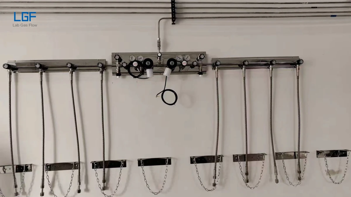
A single-bank manifold may suit an instrument that can stop safely for a cylinder change, has predictable low consumption, and is monitored by trained staff. It has fewer source paths and can be simpler to purchase and maintain. Its tradeoff is downtime when connected cylinders run low or require replacement.
Single-bank selection should be an explicit operating decision. A long analytical run, continuous environmental test, or unattended process may lose data or require a difficult restart if supply stops. In those settings, continuity may justify a reserve bank even when average consumption is small.
A single bank can still contain several cylinders in parallel to provide capacity or flow. Cylinder count is a capacity decision; the number of banks is a continuity decision. Confusing them can produce an oversized assembly that still has no independent reserve.
When should a laboratory specify a dual-bank changeover manifold?
A dual-bank manifold is appropriate when gas delivery must continue while one cylinder group is replaced or when instruments cannot tolerate a source interruption. The duty bank supplies gas during normal operation; the reserve bank becomes available when the duty bank reaches a defined changeover condition. A clear indication should show which bank is supplying and which needs attention.
Dual-bank equipment adds valves, regulators, sensing, and sometimes electrical controls. Those additions create more points to inspect and more operating states to document. A buyer should compare continuity benefit with maintenance effort, not just compare the purchase prices of one-bank and two-bank hardware.
Automatic transfer does not create an endless supply. If the reserve bank is depleted or improperly isolated, the laboratory can still lose gas. The purchasing specification should define low-bank alerts, reserve status indication, operator response, and the handover record after each cylinder change.
What is the difference between manual, semi-automatic, and automatic changeover?
Changeover terminology varies between suppliers, so the required sequence must be written down. A manual manifold requires an operator to select or open the reserve path. A semi-automatic assembly commonly transfers supply at a defined pressure condition but still requires an operator to reset or designate the preferred bank after replacement. A fully automatic arrangement may manage transfer and bank priority with controls and alarms, subject to its exact design.
| Selection point | Manual | Semi-automatic | Automatic |
|---|---|---|---|
| Supply transfer | Operator action | Pressure-driven or configured transfer | Controller-managed transfer |
| Best fit | Supervised, interruption-tolerant use | Continuity with routine staff response | Continuity with remote status or defined control logic |
| Main question | Who notices low pressure? | What must staff reset? | What happens during alarm or power loss? |
| Maintenance focus | Valves and regulator | Transfer mechanism and indications | Controls, sensors, alarms, and mechanical path |
These labels do not guarantee outlet-pressure stability or a particular fail-safe state. The buyer should request a sequence of operations covering normal draw, low duty-bank pressure, transfer, reserve depletion, power interruption where applicable, and cylinder replacement. LGF’s manual and semi-automatic manifold listing and automatic CO2 changeover listing illustrate different categories; confirm current drawings and ordering options for any project.
How should cylinder-bank capacity and peak flow be sized?
Manifold sizing starts with a gas demand schedule, not the number of cylinders visible in a photograph. List each connected instrument, its normal flow, short peak flow, hours of use, and the number of instruments that can run simultaneously. A regulator that meets average demand may still allow outlet pressure to fall during a simultaneous peak.
Usable cylinder inventory must be evaluated between the full-cylinder condition and the minimum source pressure at which the manifold can still maintain the required outlet pressure and flow. Cylinder size, fill pressure, temperature, and any residual-pressure rule affect that estimate. Dividing nominal cylinder volume by average flow is only an initial planning estimate.
Reserve capacity is a separate question. It should cover the time needed to receive, connect, and qualify replacement cylinders under the laboratory’s staffing pattern. A facility with weekend operation may need a different reserve period from a staffed weekday laboratory even if their daily gas consumption is identical.
For mixed demand, calculate credible simultaneous use rather than adding every catalog maximum or assuming all instruments use their average flow. Document the chosen coincidence assumption. That permits a meaningful comparison of supplier flow curves at the actual inlet-pressure range and required outlet pressure.
Which pressure ratings and regulator characteristics matter?
The manifold inlet pressure rating must cover the highest pressure expected from the specified gas source and connection. Every inlet component, flexible line, valve, gauge, and fitting must be suitable for that condition. The outlet-pressure range must cover the downstream line specification while preserving enough margin for pressure loss at peak flow.
A regulator should be evaluated by its flow curve and outlet-pressure behavior across the expected inlet-pressure range. A wide nominal adjustment range is not evidence of stable delivery. For sensitive analytical equipment, the owner may need an allowable outlet-pressure band during cylinder depletion and changeover, verified at the intended flow.
Pressure regulation may occur at the manifold and again near the instrument. Two-stage control can separate source-pressure variation from the fine pressure required at the point of use, but the arrangement must be engineered as a system. The laboratory gas piping design page provides broader context for line pressure, route, and downstream demand.
How do purity, materials, and connections affect selection?
High-purity gas selection requires attention to the entire wetted path: body alloy, seals, diaphragms, flexible inlets, valves, gauges, joints, and purge components. A stainless-steel body can be appropriate for many high-purity applications, but a metal label alone does not establish cleanliness, leak tightness, or compatibility with every gas. Ask for the exact wetted-material list and preparation standard for the ordered assembly.
Connections must be gas-specific and region-specific. Cylinder valve outlets, pigtail connectors, and end fittings cannot be selected by visual similarity or adapted casually across incompatible gases. The customer should provide the gas supplier’s cylinder-connection specification; the manifold supplier should identify the matching inlet assembly on the drawing.
Gas purity can be compromised during cylinder replacement if air or moisture enters an exposed source line. A suitable purge arrangement may help control that risk, but its method, medium, exhaust route, and operating sequence must be designed for the gas hazard. For sensitive service, request a documented leak-test and cleanliness acceptance method rather than relying on a generic “high purity” claim. LGF’s UHP stainless-steel changeover manifold listing is a starting point for discussing configurations, not a substitute for application review.
What changes for flammable, oxidizing, toxic, or corrosive gases?
Hazardous gases can change location, ventilation, containment, detection, shutoff, vent routing, material compatibility, and operator procedures. A manifold suitable for inert nitrogen is not automatically suitable for hydrogen, oxygen, a corrosive gas, or another specialty gas. Gas safety data, concentration, quantity, and local code must guide a documented hazard review.
Flammable gas designs may require controls around ignition sources, detection, emergency isolation, and ventilation. Oxygen service raises compatibility and cleanliness questions that cannot be solved by choosing a stainless-steel housing alone. Corrosive or toxic gas service may require enclosure, containment, compatible wetted materials, and a reviewed purge and exhaust path. Exact requirements depend on gas and jurisdiction.
In the United States, OSHA 29 CFR 1910.101 addresses compressed-gas cylinder handling, storage, and use; it does not provide a complete laboratory manifold design. Outside the United States, the project team must identify governing local requirements. LGF’s flammable-gas solution page and corrosive and high-purity gas page show why hazardous-gas selection needs separate engineering review.
Where should a manifold be installed in the laboratory supply chain?
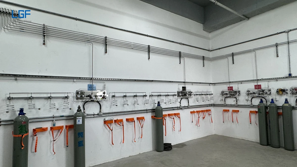
A manifold should be placed where approved cylinders can be secured, identified, accessed, and changed without interfering with clean work or emergency routes. The position should also allow reading of gauges, operation of isolation valves, inspection of inlets, and access to maintenance points. Whether the source belongs in a dedicated room, cabinet, or another controlled area depends on gas and project rules.
The outlet should connect to a distribution system designed for pressure, flow, cleanliness, and gas identification. Long runs and numerous fittings can create pressure drop and additional leak opportunities. The manifold’s outlet pressure cannot be selected independently from downstream pipe size and instrument requirements.
A project drawing should mark cylinder-bank footprint, wall mounting, service clearances, line routes, alarms, utilities, and any exhaust or purge destination. A photograph can help visualize space use, but it cannot establish that an installation complies with a code or that a similar room is suitable for another gas.
How should a new manifold be inspected and commissioned?
Incoming inspection should match the delivered manifold to its approved drawing, gas service, order code, serial or lot record, material list, pressure ratings, connection sizes, gauge ranges, regulator settings, and documentation package. A small mismatch at a cylinder inlet can stop commissioning even when the panel appears well built.
Commissioning should be performed by qualified personnel using an approved procedure and appropriate test medium. The acceptance plan may include visual and dimensional checks, pressure and leak testing, functional verification of regulators and isolation points, changeover simulation, alarm checks, and outlet-performance confirmation at representative flow. Acceptance values must come from the approved design and manufacturer documentation, not from a general article.
After testing, record the normal bank position, outlet setting, alarm setpoints, test results, as-built drawing, spare-parts list, and operator training. A handover packet makes later troubleshooting safer because it distinguishes the intended sequence from an improvised one. LGF’s specialty gas installation guidance and pipeline installation page provide related context.
What should a changeover acceptance test demonstrate?
A changeover acceptance test should demonstrate more than a visible movement from one bank to another. The approved test should record the supply pressure immediately before transfer, the outlet pressure during the event, the time or condition that initiated the transfer, and the status indications afterward. If the downstream instruments have a specified pressure tolerance, the test should show whether the actual transition stays within it at representative flow.
The test should also distinguish the duty bank from the reserve bank unambiguously. Operators must know which side is depleted, which side is supplying, and when a replaced bank becomes available again. A remote alarm is useful only if its signal reaches the intended monitoring point and prompts a defined response. For electrically controlled equipment, the approved sequence should state what a power interruption does to valve position, indication, and gas supply.
Transfer performance should be checked against the ordered model and gas path. A factory test can confirm an assembled panel, while site commissioning checks the manifold after transport, installation, and connection to the actual distribution line. Both records are valuable because a site fault may lie in a cylinder connection, downstream restriction, or control wiring rather than in the manifold hardware itself.
What maintenance keeps a manifold reliable?
A manifold maintenance plan should follow the manufacturer’s instructions, gas hazard, duty cycle, and site operating history. Operators should routinely check bank status, alarm indications, visible damage, identification labels, and pressure trends. Only trained personnel should change cylinders or investigate a suspected leak under the site’s approved procedure.
Regulators, flexible inlet lines, seals, gauges, transducers, valves, and alarm connections may need periodic inspection or replacement. The interval depends on component instructions and operating conditions; there is no universal date that fits every manifold. Changed outlet stability, a rising leak-test result, or repeated nuisance transfer deserves investigation before an instrument fails.
Keep maintenance records tied to manifold identification and cylinder-change history. These records can reveal whether an apparent supply interruption came from the transfer mechanism, an empty reserve, a closed valve, or downstream demand beyond design. LGF’s after-sales maintenance page describes wider system inspection context.
What should a B2B buyer include in a manifold RFQ?
An effective request for quotation names gas and grade, hazard classification, cylinder-connection standard, source-pressure range, required outlet pressure, normal and peak flow, number of simultaneous users, bank capacity, and required reserve duration. It states whether manual, semi-automatic, or automatic changeover is wanted and describes the required sequence rather than relying on a label alone.
The RFQ should specify wetted materials, cleanliness and leak-test requirements, purge or vent function, gauge and sensor ranges, alarm outputs, power supply if any, mounting space, ambient conditions, and downstream connection. Drawings should show the responsibility boundary between manifold, cylinder supplier, and piping contractor.
Ask suppliers to return a marked-up process diagram, bill of materials, pressure and flow evidence, installation dimensions, connection details, operating manual, test plan, and spare-parts information. Compare quotations on that common basis. An inexpensive assembly with missing purge, unsuitable connectors, or no demonstrated peak-flow performance is not an equivalent offer.
LGF’s gas product selection guide can help organize information before a model is chosen. The final specification should be reviewed by the project engineer and the facility’s responsible safety team.
How should buyers compare total cost rather than panel price?
Manifold cost includes the panel, approved cylinder connectors, regulator stages, alarms, installation, testing, training, spare parts, and future cylinder-change work. A manual manifold may be economical for supervised noncritical duty. An automatic system may justify its higher equipment and maintenance cost when lost instrument runs or unattended depletion are expensive.
More cylinders can reduce change frequency but require space, restraint, handling, and inventory management. More automation can improve visibility but adds sensors, controls, and a need to define power-loss behavior. The best value is the simplest configuration that meets documented continuity, safety, purity, and operating requirements.
Frequently asked questions about laboratory gas manifolds
Can one manifold carry several different gases?
A standard cylinder manifold should be specified for one identified gas service unless an engineered system explicitly provides segregated, approved paths. Sharing a common gas path between incompatible gases risks contamination and hazardous mixing.
Does a dual-bank manifold always prevent downtime?
No. A dual-bank manifold only supports continuity when its reserve has usable gas, its valves and changeover operate correctly, and the assembly supplies the required peak flow. Alarm response and cylinder logistics remain necessary.
Is a high-purity stainless-steel manifold suitable for every specialty gas?
No. Suitability depends on the exact wetted components, seals, concentration, pressure, temperature, cleanliness, and hazard controls. A named material grade alone is not a complete compatibility assessment.
Should the manifold control final instrument pressure?
The manifold typically establishes a stable distribution pressure. Sensitive instruments may still need a point-of-use regulator for final control. The correct arrangement depends on pressure drop, flow, and instrument specifications.
What is the first document to request from a supplier?
Request a gas-path diagram and a model-specific data sheet showing inlet and outlet conditions, connections, materials, and changeover sequence. Those documents reveal more about fit than a photograph or generic product title.
Plan a laboratory gas manifold project with LGF
LGF supplies laboratory gas source and distribution equipment for projects that need a defined gas path, reliable operation, and clear purchasing documents. For a B2B quotation, send the gas list, cylinder standard, pressure and flow schedule, changeover requirement, hazard controls, installation drawing, and expected order scope. The LGF team can review a suitable manifold configuration and related system interfaces. Contact LGF to discuss a laboratory gas manifold purchase or a larger gas delivery project.