
LGF / ABOUT US
Factory Strength & Manufacturing Capacity
Factory capability is best understood through the processes a project can specify, inspect and receive—not an unsupported annual output number.
INSIDE LGF LAB GAS FLOW
A look at the manufacturing work behind a laboratory gas system
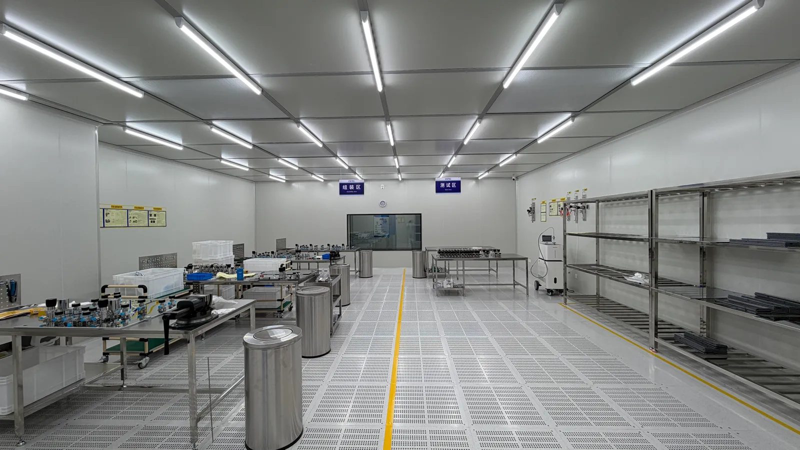
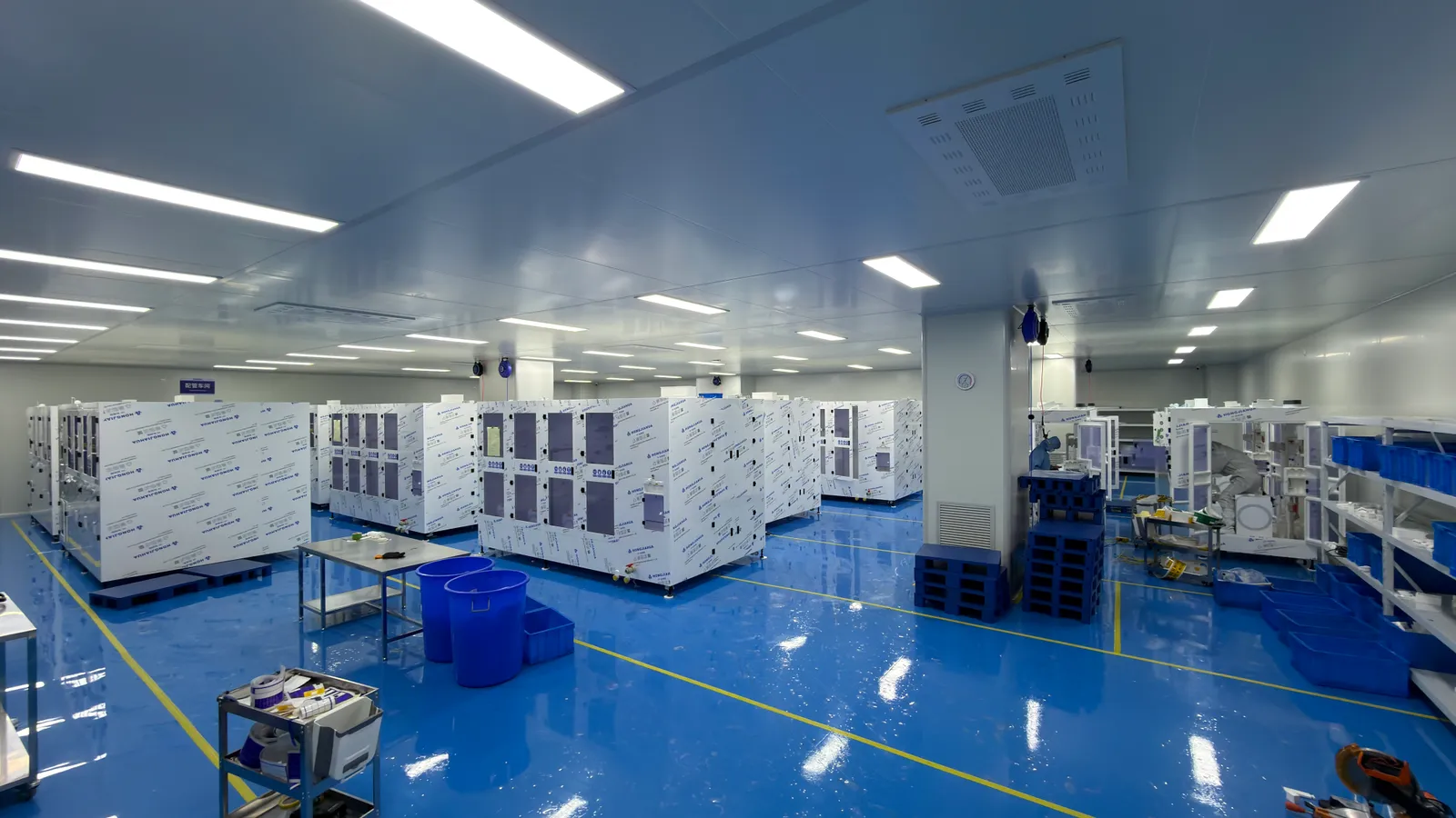
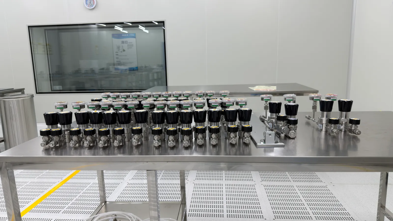
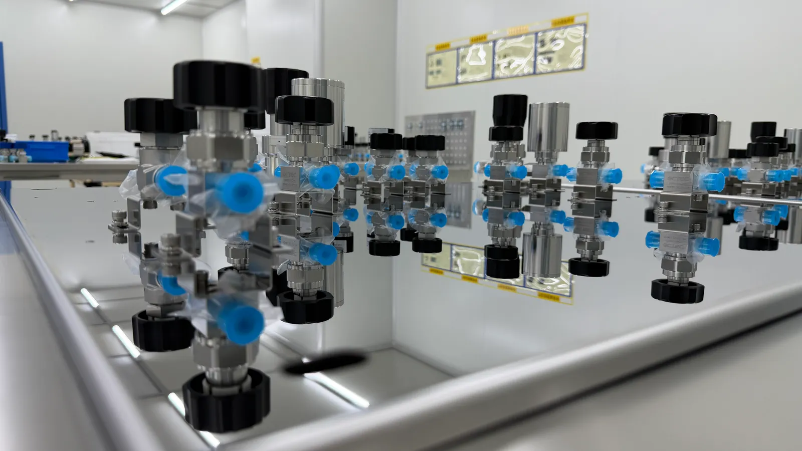
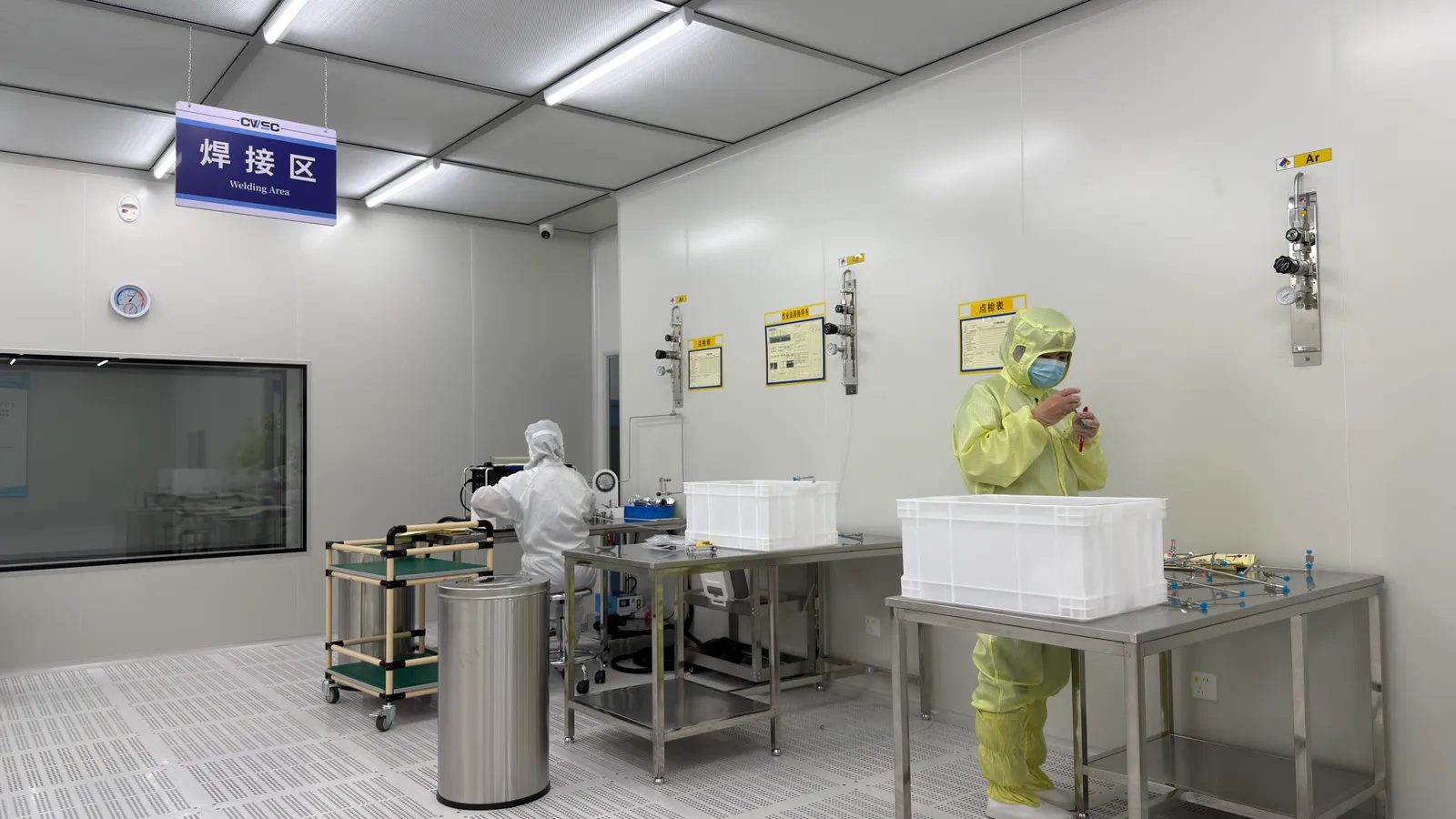
LGF Lab Gas Flow presents laboratory specialty-gas systems that depend on precision components, assembled control equipment and a clear handover to the installation team. The photographs below show clean work areas, regulator and valve assemblies, and cabinet staging. They offer a closer look at the work behind configured laboratory gas equipment; any facility classification or production commitment should be confirmed for the specific order.
For B2B buyers, capacity is a scheduling and quality question. How many assemblies of the required configuration can be completed by the required date? Which parts have long lead times? What inspection and documentation are included? These answers depend on the actual bill of materials, customization and approval cycle. LGF therefore confirms project capacity and lead time in a quotation instead of publishing a single figure that would be misleading across different systems.
01 / ENGINEERING RELEASE
Turn a gas schedule into a buildable assembly
Production begins with a defined configuration. The gas, purity, source pressure, controlled outlet range, expected flow, materials, connections, monitoring interfaces and cabinet or panel layout should be captured in approved drawings and a bill of materials. A custom laboratory gas manifold is different from a repeat component order: design review and the customer approval cycle can become the critical path.
A clear release package helps prevent substitutions that appear small but affect gas compatibility or site fit. A drawing should identify connection orientation, access for cylinder changes or maintenance, mounting points and the interface with the building route. When the design is approved, manufacturing and inspection can work against the same revision.
02 / PRECISION PARTS
Machine components to the intended geometry
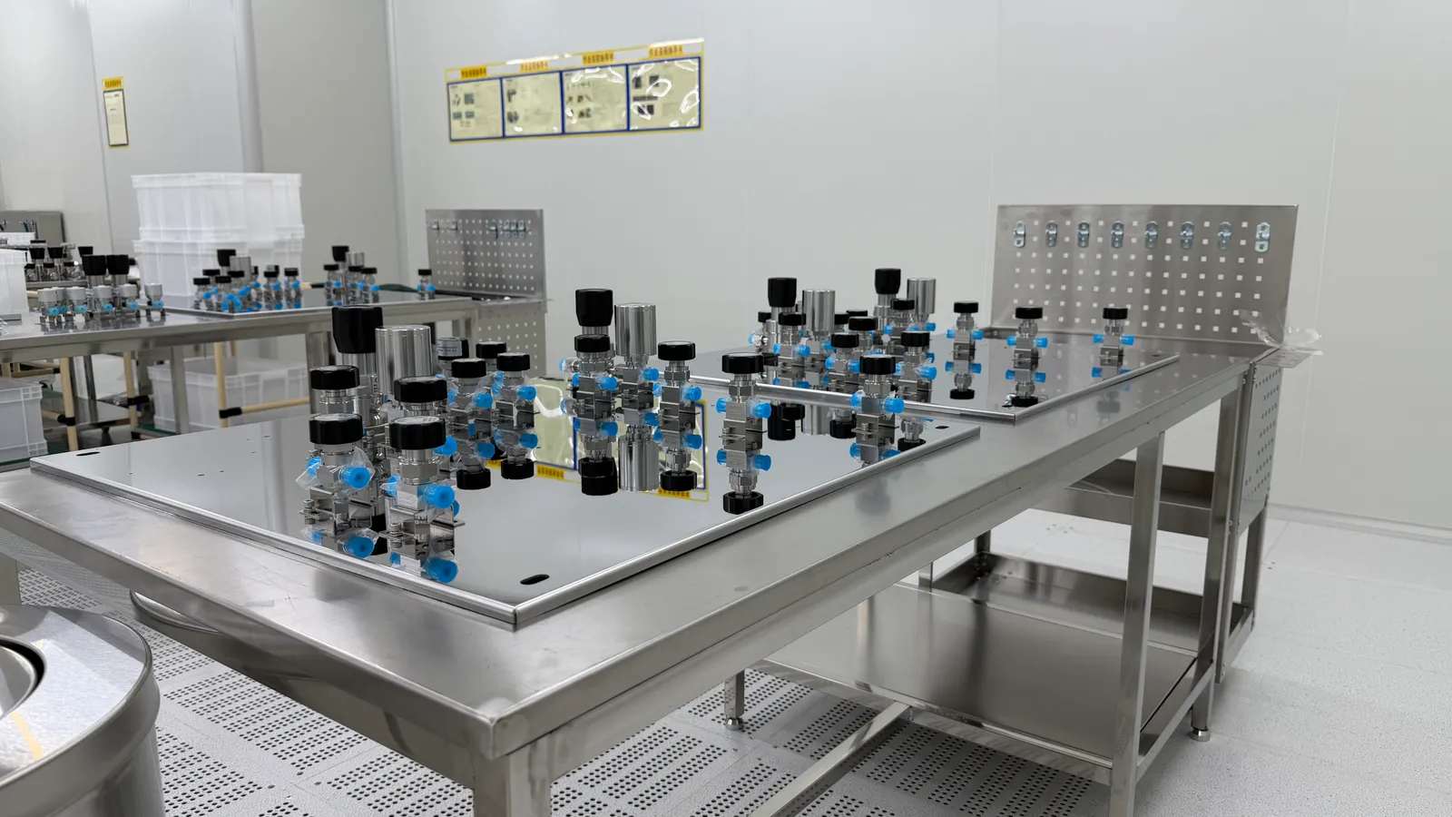
Valve and regulator components rely on dimensions, sealing surfaces and clean internal passages. The production images show prepared gas-control parts and assembled hardware. For a specific order, the appropriate checks may include dimensions, surface condition, material identity and fit with mating components. The drawing and inspection plan should state what matters to the gas path.
Machining capacity cannot be reduced to a machine count. Tooling, material availability, part complexity, finishing requirements and inspection load all affect throughput. If a project needs a non-standard connection or a special alloy, the procurement team should allow for engineering and sample approval before committing to a site installation date.
03 / ASSEMBLY ENVIRONMENT
Match handling controls to the purity requirement
The factory image library shows controlled workspaces and personnel handling equipment. A high-purity build may require defined cleaning, capped openings, protected storage, segregated parts and packaging that preserves the achieved condition. The required level should be specified for the gas and instrument rather than inferred from the appearance of a room.
For a gas cabinet or panel, assembly control also means checking the installed valve direction, regulator range, gauge scale, fitting type, labels and accessible service points. If a clean handling procedure or particle/moisture target is contractually required, its method and acceptance evidence should be agreed before fabrication.
04 / CABINETS AND PANELS
Stage complete equipment around interfaces and service access
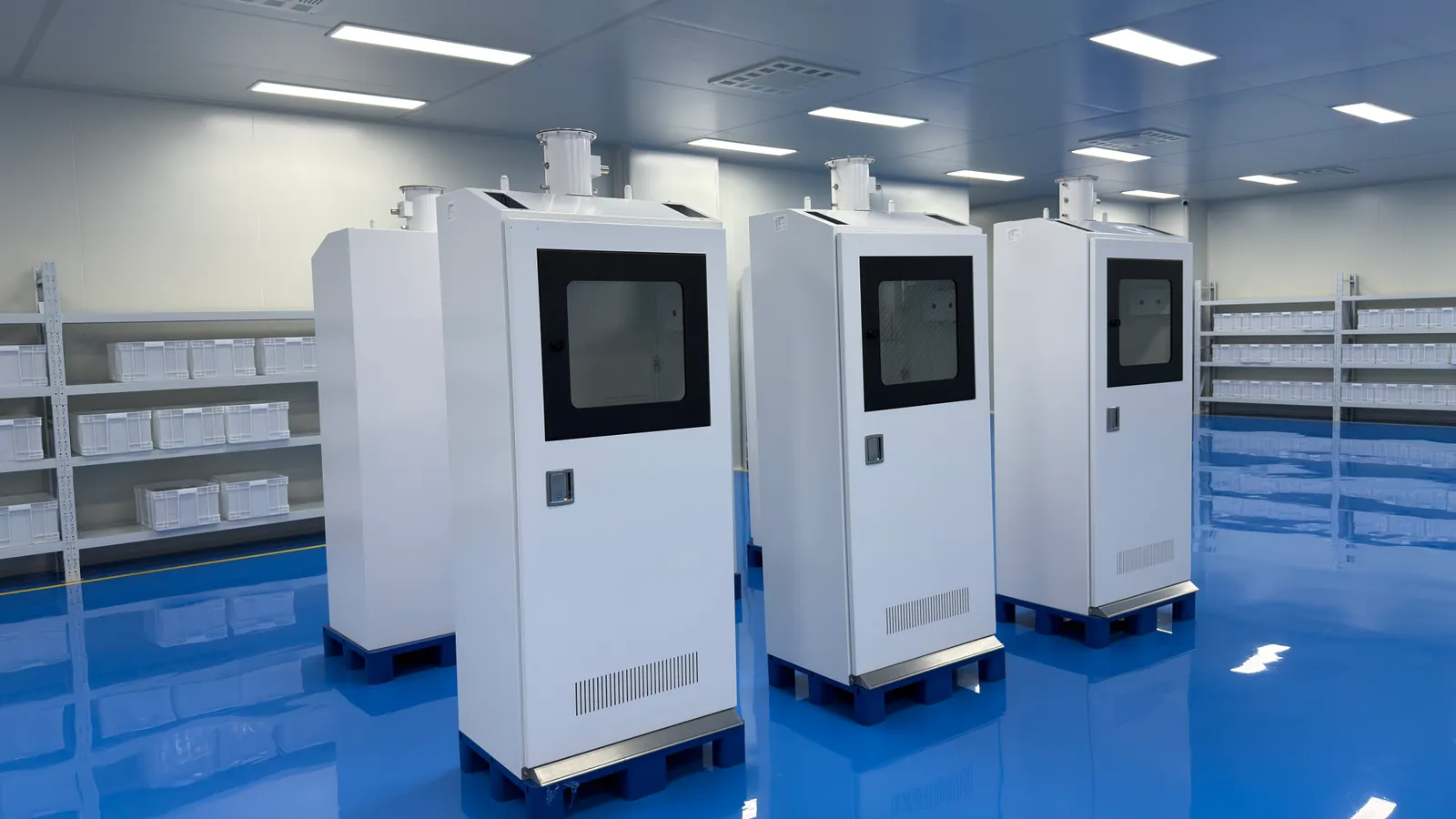
Cabinets, manifolds and distribution panels bring several components into one functional assembly. The source-side design may need cylinder connections, pressure control, purge paths, switching arrangements and interfaces to ventilation, detection or shutdown. The project engineer should confirm which of these are in the supplied equipment and which are provided by the facility.
Assembly staging should leave access to the parts an operator will actually use. This includes a readable pressure indication, clear valve identity, a practical cylinder change path and access for maintenance. Dimensions and clearance should be reviewed on the drawing before equipment is packed and shipped to the laboratory.
05 / QUALITY AND TESTING
Check the delivered configuration against the approved scope
An inspection plan should compare the assembly with its drawing and parts list. Depending on the product, this can include dimensional checks, visual inspection, connection verification, pressure or leak testing and functional checks of gauges or changeover indication. The exact method and acceptance criteria belong in the order documents. A general statement that a product is tested is not enough for a critical service.
Records should identify the assembly or circuit, drawing revision, procedure, result and responsible party. Buyers can then relate a test report to the delivered equipment. Where installation is a separate contract, factory checks and site acceptance checks should have clear boundaries so neither is mistaken for the other.
06 / PROJECT CAPACITY
Confirm lead time, packaging and handover for each order
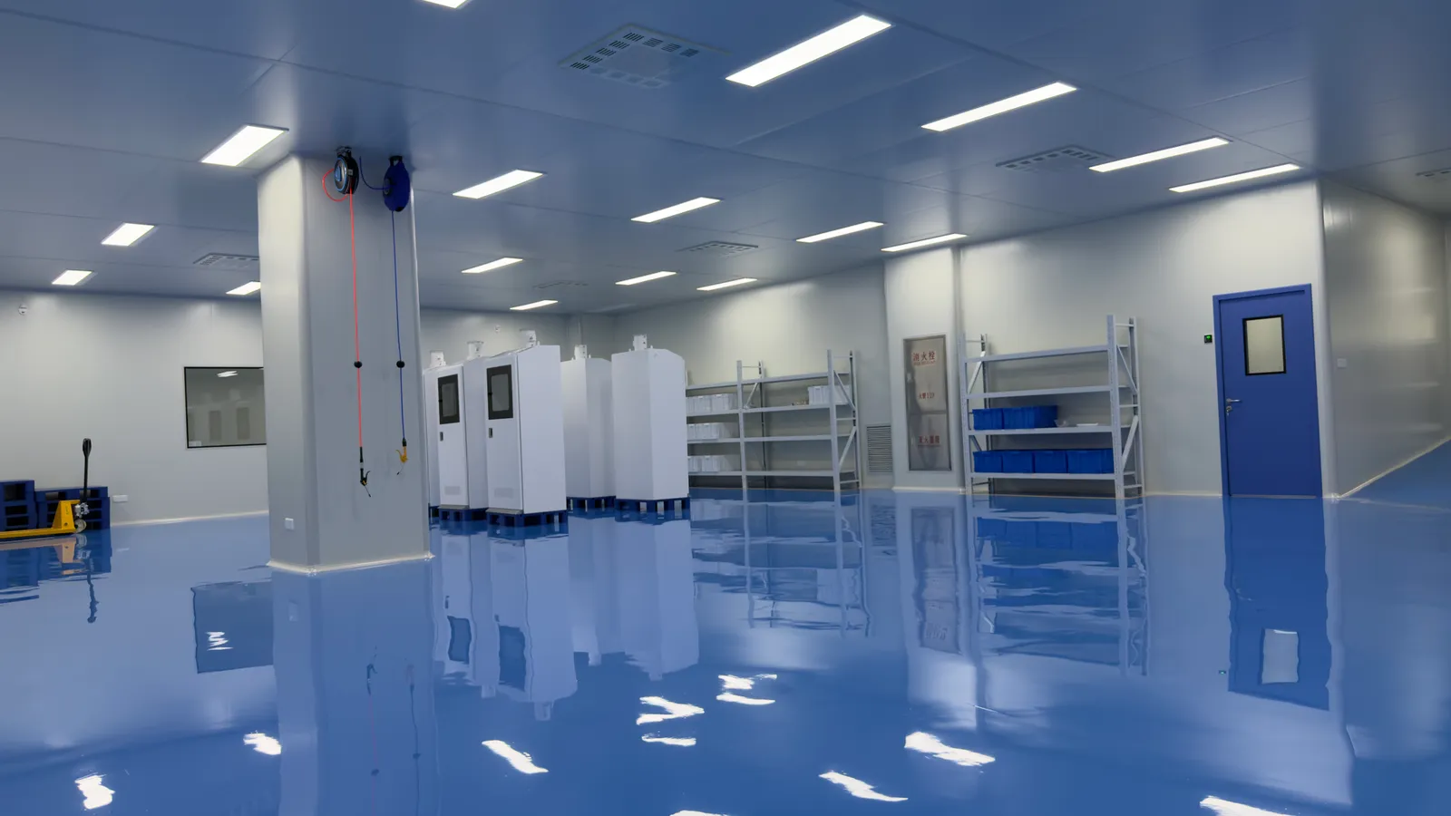
Production capacity for one standard regulator assembly does not predict the lead time for a multi-cabinet laboratory project. Drawings, non-standard parts, customer approval, testing, packaging and transport can each affect the schedule. LGF can discuss a phased delivery or priority equipment list when a laboratory has a fixed installation window, but dates should be agreed against the final scope and available resources.
A useful delivery package includes the correct equipment identification, agreed drawings, operating information, test records and any project-specific spare or maintenance data. Packaging should protect clean and finished surfaces until site installation. The receiving team should be able to check what arrived against the approved bill of materials and quickly raise discrepancies before installation starts.
NEXT-STEP CHECKLIST
What to confirm when assessing factory capacity
- Approved design and bill of materials for the exact assembly.
- Material and long-lead component availability.
- Required cleaning, assembly and packaging controls.
- Inspection and test plan with acceptance records.
- Realistic production slots and drawing-approval timing.
- Shipping, installation boundary and receiving checklist.
PRACTICAL QUESTIONS
Factory and capacity questions
Can LGF publish one fixed production capacity?
A single number would not describe different cabinets, panels, regulators and custom project packages. LGF confirms capacity and schedule against the exact order.
Do factory photos prove a cleanroom classification?
No. If a controlled-environment classification is required, request a current document covering the relevant area and scope.
What should a buyer request before placing a large order?
Ask for an approved drawing, bill of materials, inspection plan, document list, lead-time assumptions and delivery milestones.
LGF LAB GAS FLOW
Discuss capacity for a real configuration.
Send the equipment schedule, drawings, quantity and target delivery date. LGF can review the manufacturing and documentation assumptions behind a project quotation.