
LGF LAB GAS FLOW / PROJECT CASES
Centralized Gas Supply for Testing Laboratories
Testing laboratories depend on repeatable instrument conditions across many benches and methods. This case explains how centralized gas supply can organize cylinder changes, distribution branches and local controls while preserving a clear gas identity at each instrument.
AN ILLUSTRATED PROJECT REVIEW
How this laboratory gas project takes shape
Analytical laboratories may use carrier, fuel, plasma, calibration, purge and general utility gases at the same time. A centralized laboratory gas supply system is attractive when it reduces cylinder handling at benches and provides a managed place for source replacement. Its value depends on the details: each instrument still needs the correct gas, pressure, flow and connection, and operators must be able to identify and isolate a service without disturbing unrelated methods.
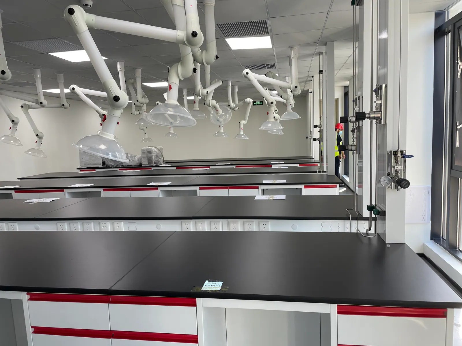
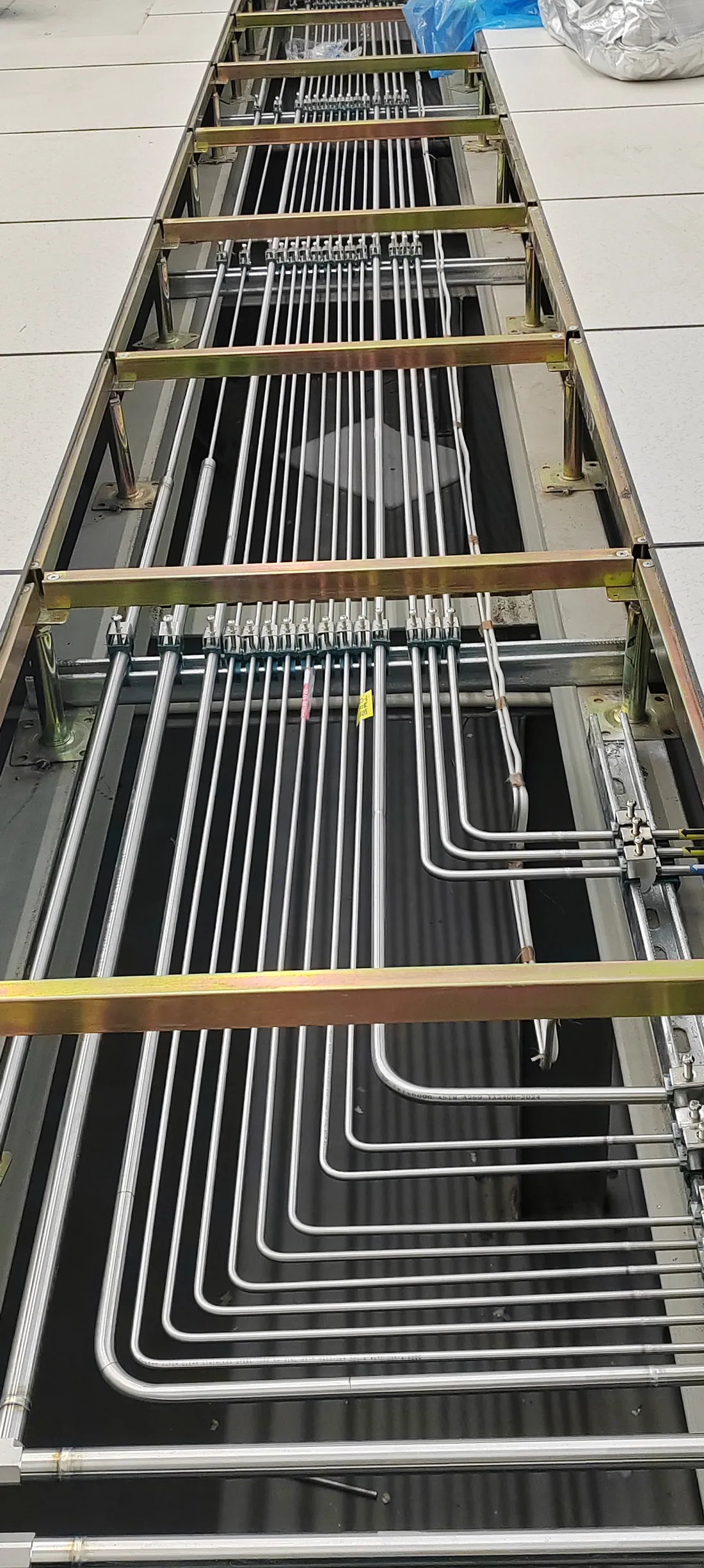
The photographs show real laboratory work areas and gas hardware. Visible equipment does not establish a particular test method, instrument model or achieved analytical result. The case therefore follows the decisions a testing organization can document when consolidating its gas supply.
01 / METHOD INVENTORY
Start with instruments, not with a manifold catalogue
A method and instrument schedule should record gas identity, required grade, inlet pressure, maximum and normal flow, duty cycle and the effect of an interrupted supply. The same nominal gas may need different quality for a sensitive analytical channel than for a general purge task. Consolidating sources before this distinction is understood can create a common header that is difficult to maintain or validate.
The schedule should also locate each instrument on a current bench plan. Where extraction arms, hoods, large analyzers and service cupboards compete for space, a point-of-use outlet must be accessible without placing tubing across a work area. Allow for equipment replacement and a safe route for maintenance personnel.
02 / CENTRAL SOURCE
Design cylinder management for actual consumption
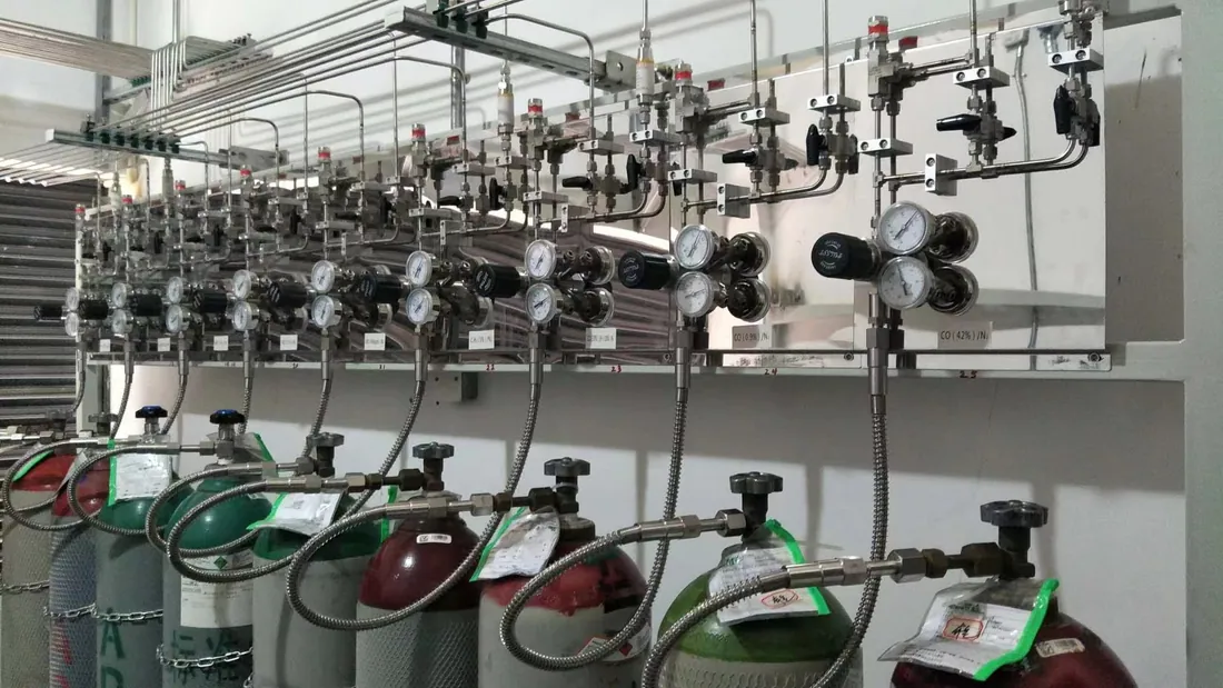
Source sizing should use simultaneous and peak demand, cylinder change frequency and the time the laboratory can tolerate an interruption. A gas manifold or changeover system may support continuous service, but its capacity and reserve logic must be calculated from the operating brief. The gas room or cabinet location also needs access for deliveries, cylinder securing, ventilation and any safety equipment the actual gases require.
A source schedule should identify cylinder connection, regulator range, bank arrangement, isolation and the person responsible for exchange. That turns a laboratory gas manifold system from a hardware purchase into an operating process. Clear procedures help prevent the wrong source being connected during a busy testing period.
03 / PIPEWORK AND TERMINALS
Carry a consistent gas identity to every bench
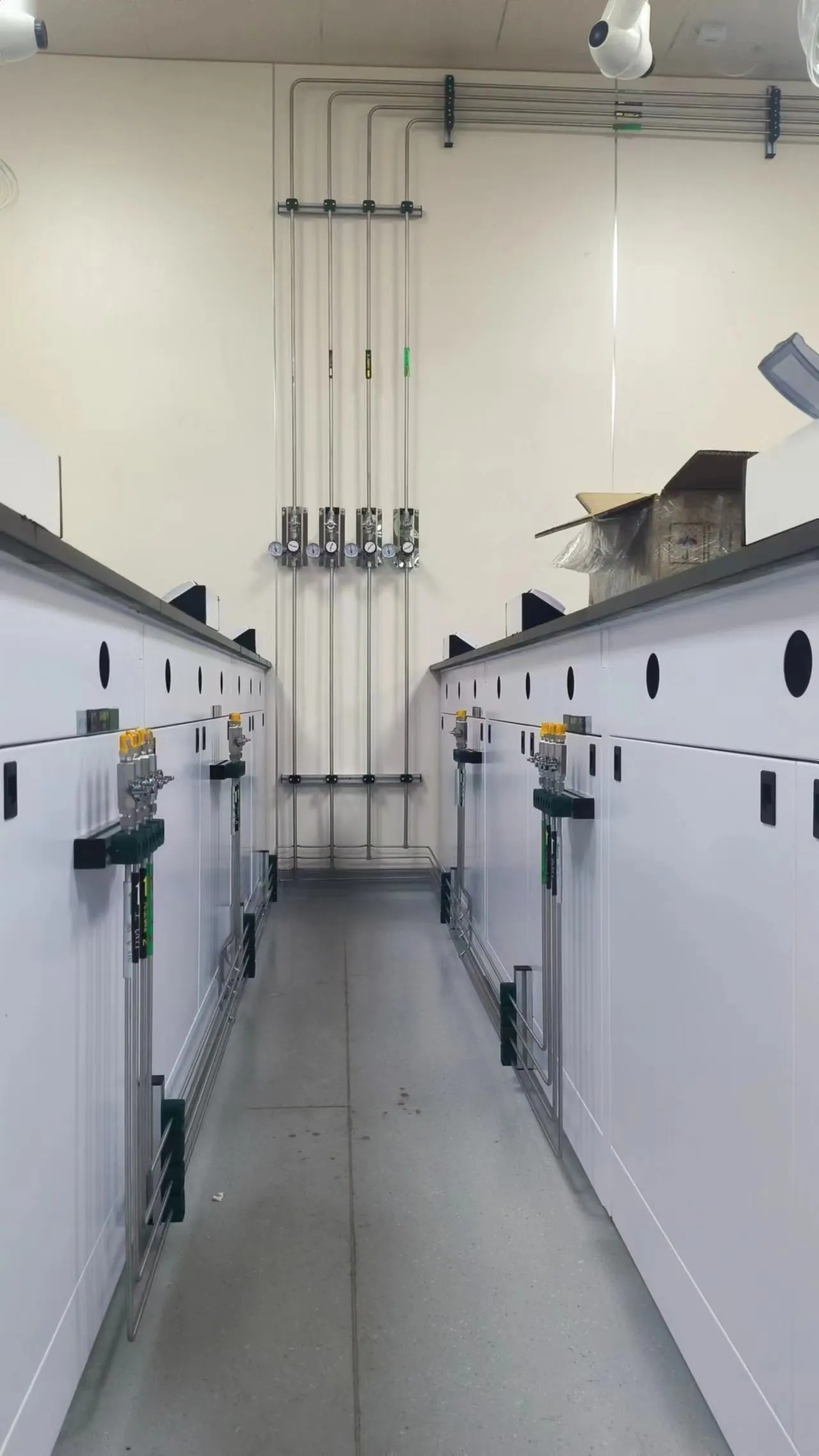
Each branch should have a tag that can be followed from source to outlet. Stainless steel laboratory gas piping, valves and fittings must be selected to suit the gas, pressure and cleanliness target. The route should protect lines from damage and leave room for inspection. Testing laboratories often change bench use, so an as-built outlet plan matters as much as the initial layout.
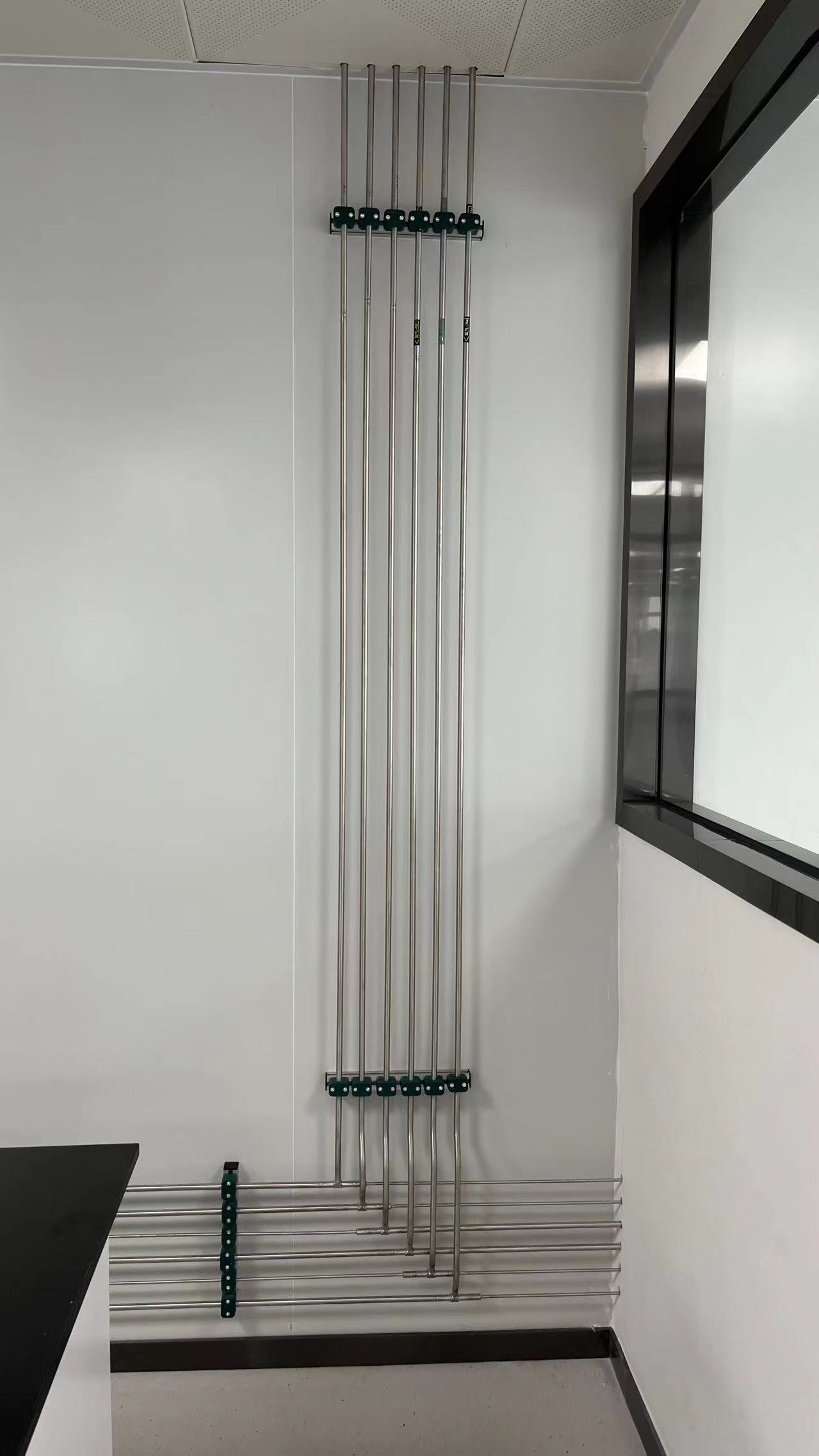
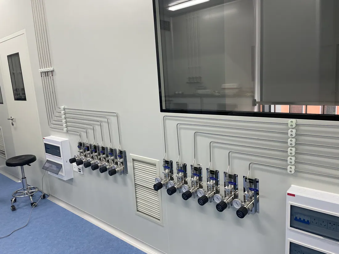
At the bench, local regulation may be needed to match an analyzer inlet even when the distribution header serves several instruments. Outlets should show gas name and permitted pressure range; connections should discourage cross-use. The photograph of wall-mounted services illustrates why a tidy termination area is valuable for operators and maintenance staff.
04 / OPERATIONAL CONTINUITY
Verify the line before a method relies on it
Before a branch is released for analysis, the commissioning plan should confirm line identity, inspection, leak-tightness, purge or cleanliness where required, and operating pressure at the actual instrument connection. Tests should follow the agreed specification and applicable local rules. The laboratory’s quality team may need separate method verification before analytical work resumes.
Cylinder-change instructions, alarm response, maintenance access and modification control should become part of the handover. A central system is easiest to operate when technicians can see which bank feeds which bench and when a spare source is available. Any later instrument addition should trigger a capacity and gas-compatibility review rather than an informal tee into an existing line.
PROJECT DECISION NOTES
Details to resolve in the project brief
Making changeover an operating decision
A fully automatic laboratory gas changeover system may suit an instrument that runs through the night, but it should be selected from actual continuity needs, cylinder consumption and the response time of staff. A manual arrangement can be workable for another gas with scheduled use and a defined reserve. The question is not whether automatic equipment is more advanced; it is whether the source arrangement keeps the required instrument conditions during replacement and gives operators a clear indication of bank status. Alarm routing, spare cylinders and service responsibility belong in the same discussion.
Outlet labels and analytical risk
An analyst sees the outlet, not the source room. Each outlet should identify the gas and line, and the operating instruction should explain local pressure control and isolation. The tubing between outlet and instrument can affect cleanliness and pressure stability; it needs a deliberate specification. When several similar connectors are close together, labeling and connection management help prevent an accidental exchange that could affect a method or damage equipment. The laboratory should record a line-to-instrument mapping that is updated when instruments move.
Comparing lifecycle requirements
The practical cost of a central supply includes source access, cylinder delivery, planned maintenance, filter and regulator replacement, periodic checks, and downtime during a future lab alteration. A bid review should request a route plan, equipment schedule and defined testing scope as well as a price. The selected design must let staff isolate a branch for service without an unnecessary shutdown of the entire laboratory. It should also leave enough space to reach valves, gauges and identification labels after all instruments are installed.
PROJECT REVIEW CHECKLIST
What the team should confirm
- Group instruments by gas, purity, pressure and simultaneous demand.
- Size source and reserve capacity from operating schedules.
- Map every source, branch, valve and outlet.
- Check the actual pressure and gas identity at the instrument.
- Document cylinder exchange and future equipment changes.
PRACTICAL QUESTIONS
Questions before procurement
Does a centralized system remove all cylinders from the laboratory?
It may reduce cylinders at benches, but the chosen source locations depend on gas hazards, building layout, consumption and local requirements.
Will one header serve every instrument using the same gas?
Only if gas quality, pressure, continuity and contamination requirements are compatible. Some instruments need a dedicated branch or additional local control.
What should a testing lab provide for quotation?
Send the instrument and method schedule, gas specifications, room plan, current source arrangement, operating hours and expected growth.
DISCUSS A SIMILAR PROJECT
Share your gas list and room plan.
LGF Lab Gas Flow can review the source, distribution and point-of-use scope for your laboratory. Include instrument inlet needs and site constraints for a useful first discussion.