
LGF LAB GAS FLOW / DELIVERY GUIDE
Laboratory Gas Pipeline Installation
Translate an approved gas-piping design into a clean, identified and tested system. Follow the work from preconstruction review and protected materials through fabrication, leak testing, functional checks and documented handover.
FROM DRAWING TO VERIFIED SERVICE
Installation is a sequence of controlled handoffs
Laboratory gas pipeline installation is not complete when the last tube is fixed to a wall. The installer must confirm the service identity, use materials approved for that gas, preserve the required cleanliness, assemble joints by the specified method, protect the line while other trades work, test each defined section and prove that the correct gas reaches the correct outlet. The final evidence matters because a hidden connection or mislabeled point of use is difficult to diagnose after a laboratory opens.
This page is a practical framework for facilities teams, laboratory managers and procurement staff overseeing installation and commissioning. It assumes an approved project design and qualified personnel. It does not replace a site method statement, local code review or a gas-specific risk assessment. For upstream decisions on routes, line sizes, material selection and safety interfaces, use our laboratory gas piping design guide. For a wider source-to-instrument architecture, see centralized laboratory gas supply.
01 / PRECONSTRUCTION HOLD POINT
Agree what will be installed, by whom and in what order
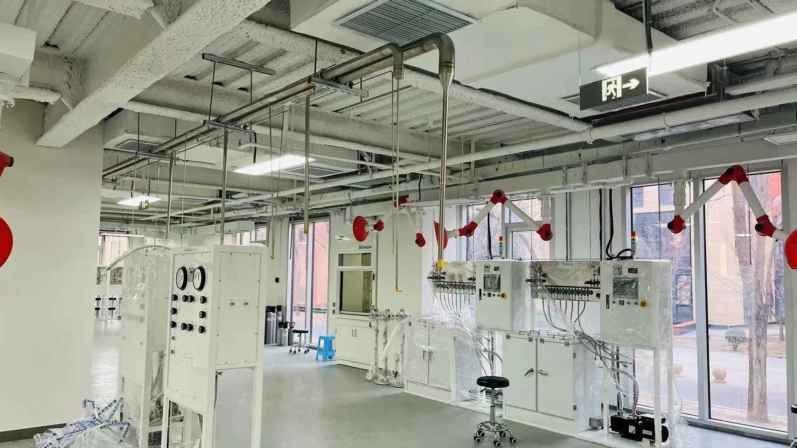
Before a contractor mobilizes, compare the issued-for-construction P&ID, gas-use schedule, route drawings, equipment interfaces and room layouts. Walk the route with the building team. Confirm that shafts, ceiling space, supports, penetrations, casework openings, cylinder areas and terminal locations are actually available. If the route has changed since design, record the change and obtain engineering approval before cutting or joining materials. A field shortcut that adds a hidden joint or moves an isolation valve can alter the risk and test scope.
Define the installation boundary. Who supplies the manifold, regulator, cabinet, pipe, terminal panel, detector and instrument flex connection? Who wires a valve to the alarm panel? Who witnesses tests and approves the gas for use? The answer should appear in a responsibility matrix and sequence, not only in a purchase order. Agree inspection hold points before walls and ceilings close, and identify the documents needed for each stage.
For an operating laboratory, plan outages, temporary service, cylinder handling and access control with the users. Segregate work on an existing line from the new one, confirm its gas identity and treat unknown lines as unverified until investigated. A small new branch can disrupt several rooms if the shutdown boundary is unclear. This preconstruction review is the strongest opportunity to prevent expensive rework and unsafe assumptions.
02 / RECEIPT AND CLEANLINESS
Protect the specified material from arrival to final connection
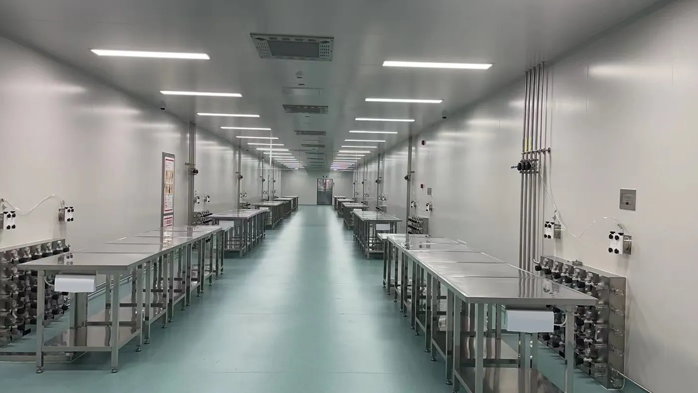
Check delivered tubing, fittings, valves and pressure-control components against the approved material schedule. Verify size, material grade, pressure rating, connection series and any required cleanliness or traceability records. A part that looks similar can have a different seat, seal or service rating. Keep each gas service separate and clearly marked. Do not substitute a tube or fitting because it is immediately available on site; document the proposed change for engineering review.
For high purity gas piping, the condition of the inside surface matters as much as the outside appearance. Maintain end caps or sealed packaging until fabrication, keep components off dirty surfaces and control tools, cutting fluids and cleaning agents. The required handling level should come from the service class; a routine utility line and a sensitive analytical carrier-gas line can need different controls. If a component is dropped, opened in an uncontrolled area or exposed to oil or moisture, assess it before installation rather than assuming a later purge will fix contamination.
Store materials so identification and records survive site work. Link batch or heat data to the sections where traceability is specified, and separate rejected items physically. Review the planned joint method with the installation team: weld preparation, purge, brazing, compression assembly and inspection all have different equipment and competency needs. A credible lab gas piping installation contractor should explain how the crew will protect cleanliness and verify every connection, not merely state that it has installed stainless tube before.
03 / ROUTE AND SUPPORTS
Install a route that can be inspected and maintained
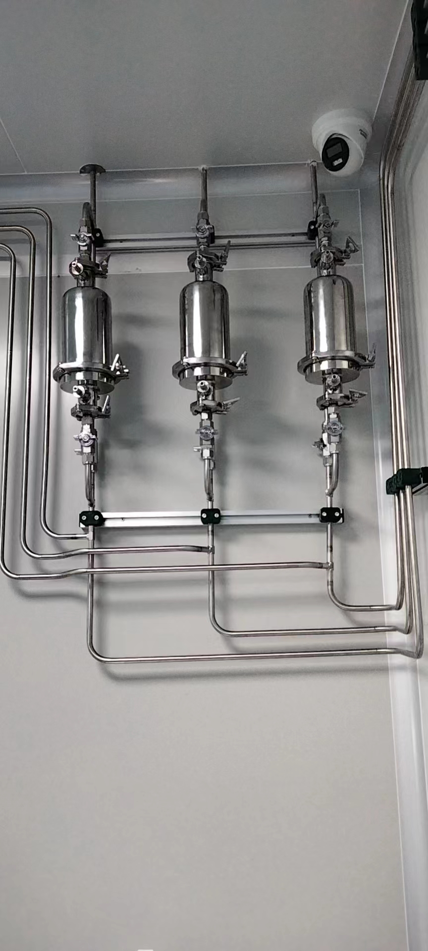
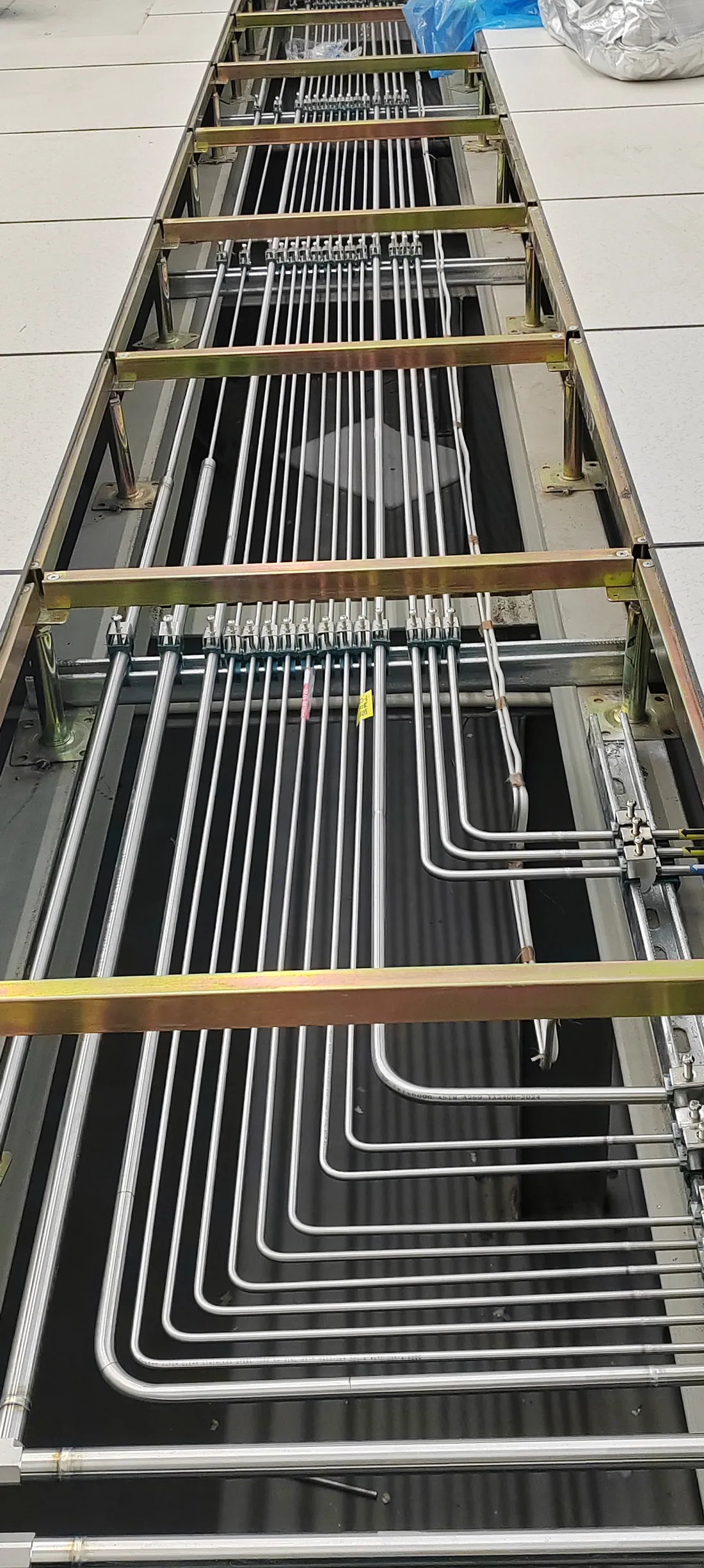
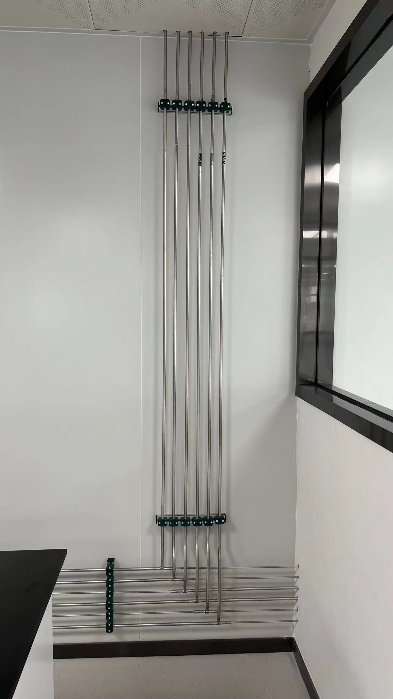
Set out the line from fixed reference points and approved elevations. Follow the coordinated route through walls, ceilings and service spaces, maintaining access to isolation valves, joints and test points. Install supports and sleeves suited to the tube, building movement and local requirements. Avoid loading delicate regulator or panel connections with unsupported pipe weight. Where lines cross fire barriers, coordinate the penetration system with the building team rather than leaving sealing to a later trade.
Keep the service legible while several trades share a ceiling. Confirm the intended separation from electrical, ventilation, drainage and incompatible services. A neat bundle is not automatically a safe or maintainable one: future technicians need to know which line they are isolating, and an inspector must be able to see the joints specified for examination. Mark service identity at points required by the project specification and before covers hide the route. Photograph concealed sections and record dimensions for the as-built set.
High purity gas pipeline installation also needs a practical connection strategy. Plan bends and prefabricated sections to minimize unnecessary joints and dead ends while still allowing thermal movement, building access and component replacement. A tray, chase or raised floor can protect the line, but only if the team can inspect it at the right hold point and preserve access where future intervention is expected. The site engineer should approve field deviations before they become permanent.
04 / JOINTS AND SYSTEM ASSEMBLY
Make fabrication traceable to the approved method
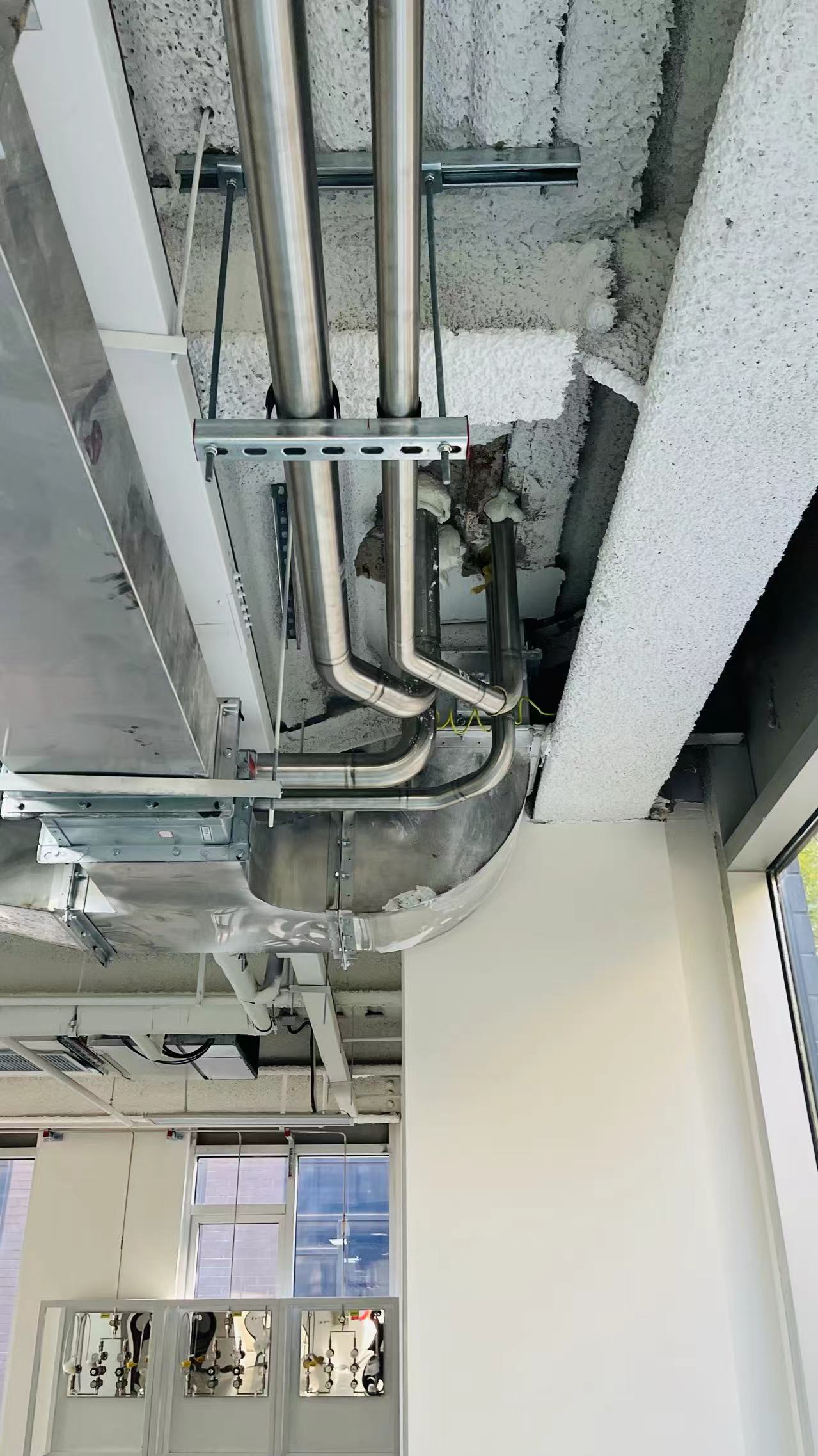
Each joint should be assembled by the method specified for its service: for example, an approved welded stainless system, a suitably designed brazed system, or an accessible mechanical tube fitting. These are not interchangeable techniques. The required method depends on the material, gas, pressure, purity, inspection access and owner standard. If orbital welding for lab gas piping is specified, confirm machine setup, shielding or purge, tube preparation, qualified personnel and the inspection records required by the project. A visually tidy bead alone does not prove the inside of a high-purity line is acceptable.
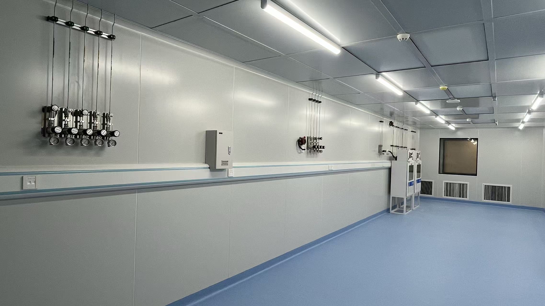
Control orientation and torque on valves, regulators, check valves, filters and flow-direction components. Install panels and manifolds level and accessible, following the approved drawings and manufacturer instructions. Protect gauges and sensitive instruments during any pressure test that could exceed their rating. Keep relief and vent lines separate where required; a relief device that discharges to an unreviewed location is a system defect even if the supply line is leak-tight.
Record joint locations and installer or procedure identifiers where the specification calls for them. Verify that the right gas-service parts are on the right line before closing a section. Material and joining requirements vary by gas and facility. Establish the method in the project documents, then follow and inspect it consistently.
05 / TEST, PURGE AND FUNCTION
Test the built network in a documented sequence
Agree the test plan before introducing any medium. Separate strength or proof checks, tightness or leak checks, purge and cleanliness verification, gas identity checks and functional tests; each answers a different question. Define the test section boundaries, instrument isolation, measuring equipment, test medium, pressure, duration, acceptance criterion, witness and record form. Numbers taken from another project may damage components or fail to reveal a relevant leak. The applicable engineering specification and governing authority control the actual values.
For many laboratory systems, clean, dry inert gas is used in a controlled test and purge sequence. Very tight services can justify helium leak testing, but the detection method needs a defined sensitivity, calibration and acceptance threshold. Test media and leak-proving methods vary by service; these choices are project-specific, not universal settings. Never use a flammable or toxic process gas as an improvised leak-search medium.
After a section passes, verify the assembled system at each outlet: correct service identity, intended pressure range, direction of flow, regulator operation, isolation boundary and any changeover or alarm response. Check that purge and vent discharge locations are the approved ones. A pressure-hold result alone cannot detect a cross-connected line or a detector that is not wired to its shutoff valve. Record failures, repairs and retests so the handover shows the final accepted condition.
06 / COMMISSIONING AND HANDOVER
Deliver an operable system, not only completed pipework
Commission the gas path with the laboratory user, facilities operator and responsible safety or engineering reviewer. Confirm the source can be changed or replenished as intended, the distribution path supports real instrument demand, local regulators and valves are labeled, and abnormal events produce the agreed response. For gases requiring detection or ventilation, test the interface as a connected sequence rather than checking only that each device powers on. Record the initial settings and who is permitted to alter them.
Provide an as-built P&ID and route plan, outlet and valve schedule, material and joint records as required, pressure and leak test sheets, purge or cleanliness results, alarm cause-and-effect checks, operating instructions and maintenance responsibilities. Include the location of spare parts and the process for a future instrument change. Train the person who will actually handle cylinder changes and first-response isolation, not only the project representative signing the completion sheet.
Do not treat future changes as minor plumbing. A new gas, different cylinder connection, higher flow or relocated instrument can invalidate a material or pressure assumption. Preserve a change-control path that asks for a fresh compatibility and hazard review, updates labels and drawings, and retests the affected section. The installation record becomes the starting point for that decision. LGF Lab Gas Flow can discuss the equipment and project scope, while final acceptance remains with the responsible project parties.
PRACTICAL PROJECT CONTROLS
Hold points that prevent hidden defects
Put these reviews in the method statement and construction schedule so the right person can see the work before it is concealed or put into service. The exact inspection plan belongs to the approved specification, but a clear sequence helps purchasers compare laboratory gas piping contractors and prevents a final-day test from carrying the entire quality burden.
Route release
Verify the issued drawings, service identity, field clearances, supports, penetrations, access to valves and the interface with casework and other trades. Record approved deviations before fabrication.
Material and joint release
Check tubing, fittings and seals against the gas service. Review protected ends, cleaning controls, joining procedure, qualifications and any required sample joint or record format.
Concealed work inspection
Inspect visible joints, branch identity, supports, sleeves and photographs before closing ceilings, wall cavities or raised floors. Update the route mark-up while the work is still accessible.
Test and service release
Witness the approved tests, repair and retest failures, verify correct gas at every point of use, demonstrate safety interfaces and receive the as-built and training package before operation.
WHAT TO REQUEST IN A QUOTATION
Compare the scope behind the price
Laboratory gas piping system installation costs depend on route length, number of services and outlets, access, shutdown work, material and cleanliness class, joining method, testing scope and site documentation. A low quoted pipe rate does not tell you whether the installer included ceiling access, approved supports, purge gas, calibrated equipment, detector integration or as-built records. Ask bidders to respond to the same drawings and list assumptions and exclusions.
For high-purity or hazardous services, request the proposed test and cleaning method as part of the quotation. An installer should name the point at which its responsibility ends: for example, at the cabinet outlet, at a point-of-use panel or at the instrument connection. Ask who coordinates system-wide verification when several suppliers contribute components. These boundaries are where commissioning gaps often occur.
Use the design guide to complete the performance brief first. If the design remains conceptual, request a separated design or survey phase instead of forcing a fixed installation price based on unknown routes.
- Issued gas-use schedule and P&ID, including each service boundary.
- Route drawings, elevations, supports, access and outage assumptions.
- Tube, fitting, valve and panel schedule with approved alternatives.
- Joining and cleanliness procedures, crew competency and inspection records.
- Pressure, leak, purge, identity and alarm-function test plan.
- As-built drawings, operating instructions, training and warranty scope.
TWO COMMON PROJECT TYPES
Installation priorities change with the working laboratory
Protect the sequence across trades
Many gas routes are easiest to inspect before ceilings and casework are finished. Coordinate penetrations, access and test windows with the construction schedule. Preserve caps and cleanliness while nearby dusty work continues, and release each area only after the required inspection and documentation.
Control the transition from old to new
Survey existing services, confirm gas identity, define a shutdown boundary and communicate it to instrument owners. Prefabricate where practical, then test the new section before tie-in. Recommission affected outlets and issue updated labels and records so the users do not rely on obsolete drawings.
Keep a clean chain through every joint
Trace cleanliness from sealed tube through cutting, joining, inspection and purge. Agree what evidence proves the delivered service meets the instrument requirement. A clean cylinder alone does not protect an open or contaminated construction route.
Demonstrate the integrated response
Verify the approved ventilation and detection interfaces, source isolation, alarms, purge path and operator procedures before process gas is introduced. The test sequence should be witnessed by the responsible facility and safety representatives.
FREQUENT INSTALLATION QUESTIONS
Questions that make the acceptance plan clearer
Is a pressure hold enough to accept a gas line?
No. It establishes one part of integrity under specified conditions. Acceptance may also need service identification, leak localization, cleanliness or purge evidence, outlet performance and functional tests of valves, alarms and changeover equipment.
When is helium leak testing appropriate?
When the project sets a very tight leak requirement and a calibrated method with a defined acceptance limit. It can be valuable for sensitive or hazardous services. The engineer should decide the method and test boundary; it should not be sold as a generic add-on without a performance need.
Can existing pipe be reused during a renovation?
Only after its gas identity, material, condition, route, pressure rating and cleanliness are verified against the new service. Unmarked or undocumented lines require investigation. Any approved reuse should be included in the revised drawings and test plan.
Who should approve a change made on site?
The responsible design and facility representatives should review a proposed change to the route, material, joint method, valve location or safety interface before it is built. The installer should document the final condition in the as-built package.
CONTINUE THE PROJECT
Connect installation to design and equipment
PREPARE A CLEAR INSTALLATION SCOPE
Send the drawings, gas list and site conditions
Share the services, room plan, number of outlets, approved materials, project stage and expected shutdown windows. LGF Lab Gas Flow can review the required gas-control equipment and discuss the installation and commissioning interfaces with your team.