
LGF LAB GAS FLOW / ENGINEERING GUIDE
Laboratory Gas Piping Design
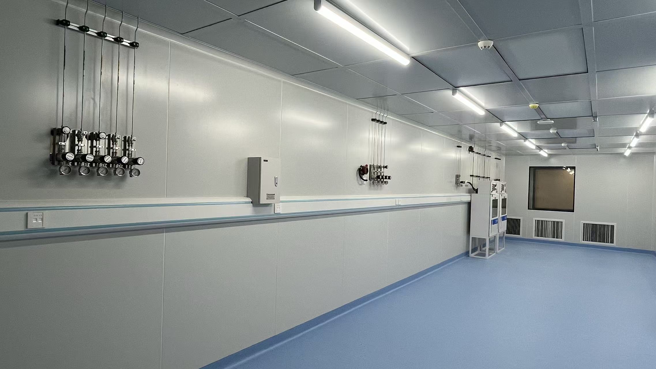
Plan a clear, compatible gas path before the first tube is installed. From the gas-use schedule and pressure budget to routes, materials, isolation and handover, each decision should support the instrument at the point of use.
DESIGN BEFORE PROCUREMENT
A laboratory gas line is only as useful as its last connection
Laboratory gas piping design connects a known source to a defined instrument demand. It must preserve an appropriate pressure and gas quality along the whole route, provide accessible isolation, and remain understandable to the people who operate the laboratory later. The drawing is therefore more than a line on a floor plan. It is an agreement between laboratory users, facilities engineers, safety staff, the gas supplier and the installer about what each line carries and what happens when the system changes.
This guide focuses on decisions made before field installation. It is distinct from our centralized laboratory gas supply guide, which compares overall source arrangements, and from our pipeline installation guide, which covers construction, testing and commissioning. The right materials and acceptance criteria depend on the actual gas, required purity, site conditions and governing requirements. A project engineer should approve the final specification.
01 / DEFINE THE DUTY
Build a gas-use schedule that an engineer can size
Start room by room, then instrument by instrument. For each outlet record the gas or mixture, cylinder or bulk source, required purity at the instrument, nominal and peak flow, inlet pressure range, operating hours, expected simultaneous use and the connection type. Add the location of each instrument and any future position already included in the project. “Nitrogen to six benches” is not enough: one bench may need a steady low-flow carrier gas while another has a short high-flow purge. The pipe size and regulation strategy depend on the combination, not only the number of outlets.
Ask which parameters come from the equipment maker and which are still assumptions. A gas supplier’s cylinder grade does not by itself establish the grade delivered after a long, poorly selected distribution line. Likewise, a regulator’s outlet setting does not prove that the farthest instrument sees the required pressure when several branches draw gas at once. Mark these uncertainties on the schedule so they become explicit design checks rather than surprises during commissioning.
Include normal operation, cylinder change, maintenance isolation and credible loss-of-supply conditions. If uninterrupted experiments matter, identify where standby supply or automatic changeover is needed and which instruments may stop safely. If research programs change frequently, provide a controlled method to label, document and approve future outlets. This schedule becomes the reference for the piping and instrumentation diagram, equipment selection and acceptance plan.
02 / SOURCE TO PRESSURE STAGES
Draw the complete path from supply to instrument
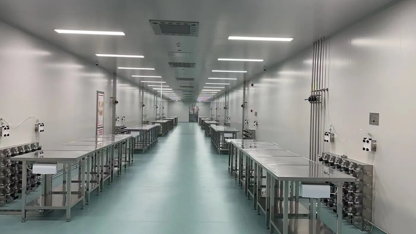
A useful laboratory gas piping system design begins at the source connection, not at the corridor wall. Show cylinders or bulk supply, manifold or cabinet, changeover arrangement, primary pressure control, relief and vent destinations, main lines, room isolation, local regulators, purge interfaces and the final point of use. Show the service boundary between supplied equipment and building services. This prevents a gap in which each contractor assumes another party will provide a valve, sensor, connection or test point.
Set a pressure budget for each representative route. Begin with the expected source and regulator behavior, then account for line length, fittings, valves, filters, local control and the minimum pressure required by the instrument. Evaluate peak simultaneous demand and the most remote outlet. A larger tube can reduce pressure loss but may increase cost, internal volume and purge time; a smaller tube may be attractive to buy yet fail at peak use. The goal is a documented balance, not a default diameter copied across every gas.
Place pressure regulation where operation and maintenance make sense. A common primary stage may serve a distribution main, while local control is needed when instruments require different delivery pressures. If one source serves multiple rooms, decide how to isolate a room without shutting down the whole building. Verify adequate pressure after line and fitting losses, and provide a clear room-level shutoff strategy where required by the project.
03 / ROUTE AND HYDRAULICS
Coordinate the route with the building, not just the plan view
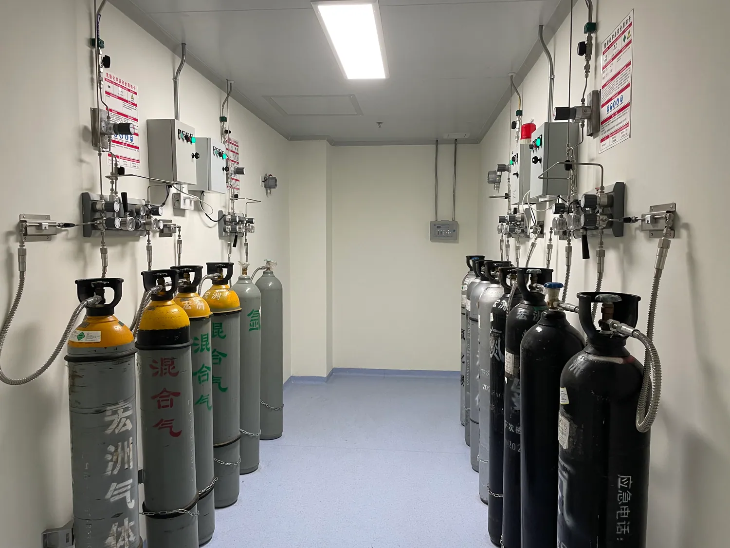
Trace the proposed line through shafts, service corridors, ceiling voids and laboratory rooms. Check structural members, fire barriers, electrical trays, ventilation ducts, casework and future access panels in three dimensions. A tidy floor-plan route can be impossible to install above a finished ceiling or can put a critical joint where no one can inspect it. Record elevations, supports, penetrations, isolation locations and the transition to the instrument. Avoid unnecessary joints and dead legs where the service and installation method allow.
Pipe sizing requires the gas properties, operating and design pressures, flow profile, equivalent length of fittings and tolerable pressure loss. The most remote outlet is a useful check, but a nearby branch with simultaneous high flow may be just as important. For a high-purity laboratory gas system, consider how line volume, cleanliness and start-up purging affect the delivered quality as well as pressure. For a renovation, verify existing pipe identity and actual route before treating an old drawing as a reliable source of dimensions.
Decide early whether a line is exposed, concealed, in a service chase or protected by a secondary enclosure. That choice affects installation sequence, inspection access, labeling and the ability to change the system later. A route near a door or service aisle should leave equipment and emergency controls accessible. Fire-rated penetrations and any required separation from incompatible services need local review. Mark the locations where an installer must stop for inspection before ceilings or walls close.
04 / COMPATIBILITY AND PURITY
Specify materials and joining by service class
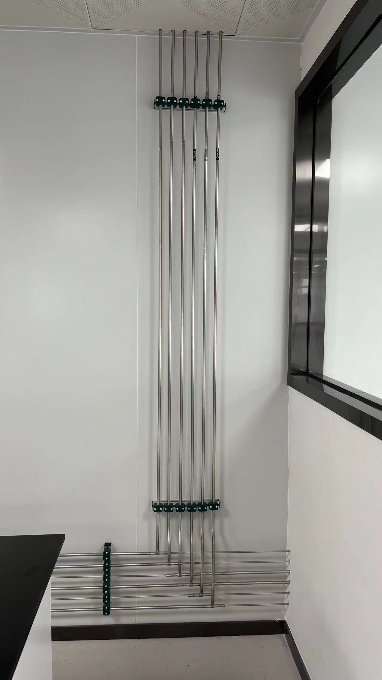
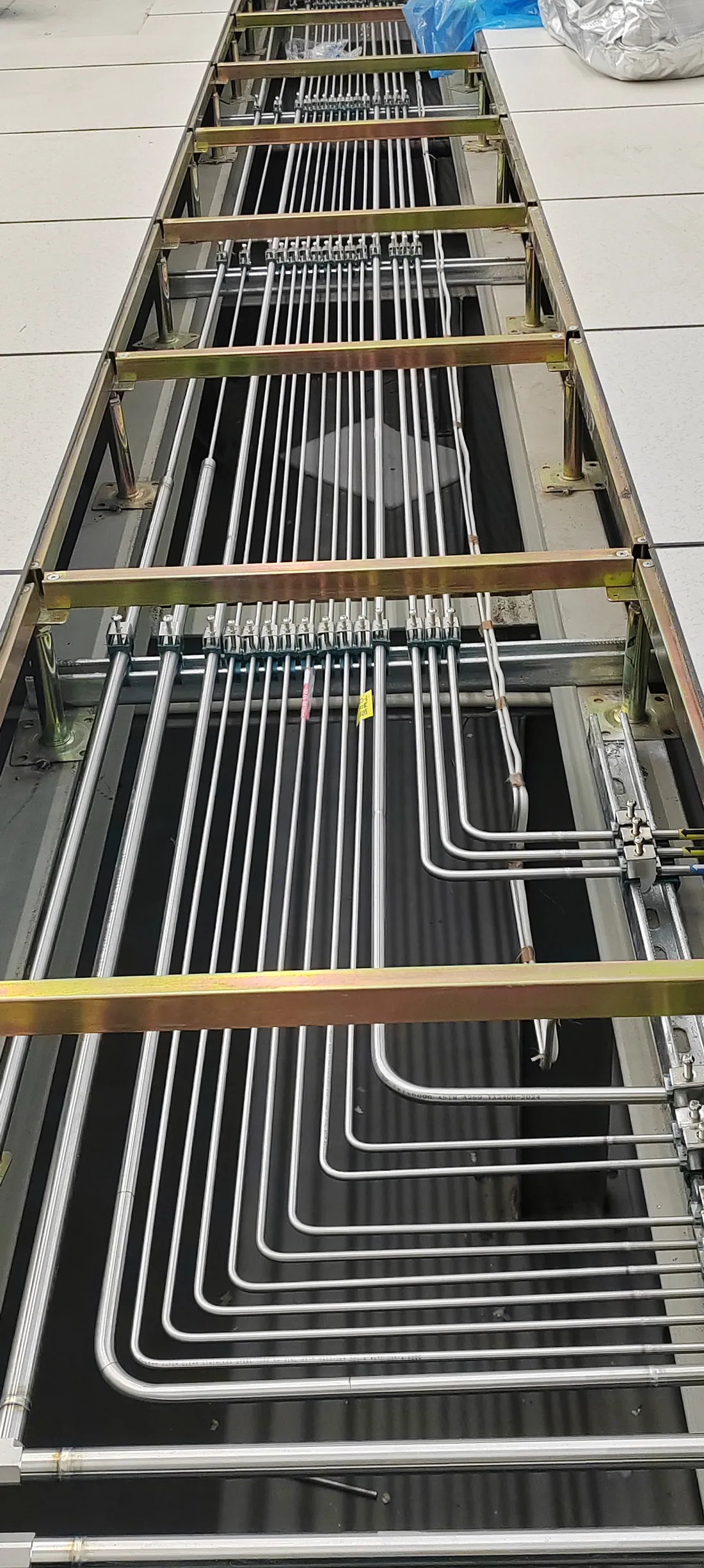
“Stainless steel laboratory gas piping” is a starting phrase, not a complete specification. Select the tube, fittings, valve internals, seals and regulator wetted surfaces against the actual gas chemistry, pressure, temperature and purity requirement. In demanding high-purity or ultra-high-purity service, a documented 316L stainless steel laboratory gas line and controlled joining practice may be appropriate. Other laboratory services can use different approved materials. Approved materials vary by gas service and project specification; the project service class decides.
Define the finish and cleanliness level that the instrument needs, how tubing is capped and stored, who may open a clean component, and how fabrication debris is excluded. Avoid vague language such as “clean pipe.” Ask the bidder to identify tube grade, surface condition, fitting series, joint method, weld or braze procedure where relevant, traceability and inspection records. Orbital welding may be specified for a high-purity stainless line, but it is not an automatic requirement for every gas. A compression fitting may be practical at an accessible serviceable point; a concealed joint can call for a different approach.
Separate the design of hazardous or corrosive gases from ordinary inert utilities. A compatible metal alone is not enough if a release could affect a shared corridor, instrument bay or another gas line. The risk review may require a cabinet, ventilated enclosure, monitoring, secondary containment, dedicated vent path or different source location. Avoid promising that one material choice makes an entire line safe: safety depends on the assembly, route, controls and operation.
05 / ACCESS AND POINT OF USE
Make each branch legible to operators and maintainers
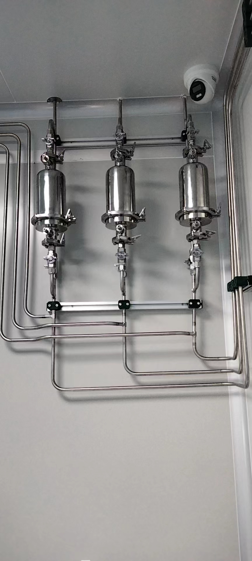
Design the line around the moment a researcher connects an instrument and the moment a technician must isolate it. The outlet location should be accessible without moving heavy equipment, and its label should clearly identify the gas. The last connection should match the instrument requirement and avoid an improvised adapter chain. If a flexible connection is allowed, specify the compatible assembly and an appropriate practical length. Define where the laboratory user’s responsibility ends and facility maintenance begins.
Place room or branch isolation valves where authorized staff can find and operate them under normal and abnormal conditions. Add local pressure indication and control where they support troubleshooting or instruments with different supply needs. For a shared laboratory, consider whether a valve should interrupt a single instrument, a bench, a room or the whole main; each boundary has a different operational cost. Show these boundaries on the drawings and on the valve schedule rather than expecting staff to infer them from pipe color.
Line identification should remain clear after renovations, equipment replacements and ceiling closure. Identify permanent piping at the supply, along the route and at discharge points as required by the project. The local code and owner standard decide exact labels and intervals. A change-control record should connect every outlet number to its source, gas identity, pressure range and test history. This makes a future modification safer and faster to evaluate.
06 / SAFETY AND ACCEPTANCE
Write the verification plan into the design package
Where a gas presents a fire, toxicity, oxygen-displacement or corrosion hazard, coordinate the pipework with the building’s ventilation, detection, alarm and emergency isolation strategy. Define what each detector observes, what action follows a signal, which valve closes, what remains powered and how staff know the system state. The correct arrangement is determined by the gas inventory, room design, applicable standards and authority having jurisdiction. A pipeline drawing without these interfaces is incomplete for a hazardous service.
Specify the acceptance evidence before selecting a contractor: material certificates where needed, approved drawings, fabrication and joint records, visual inspection points, pressure and leak test methods, purge and cleanliness checks, outlet identification, alarm function tests, as-built route drawings and operator training. Do not copy a single pressure-test value from another project. The test medium, pressure, duration and acceptance limit must match the approved design and protect sensitive downstream devices. Helium leak testing for laboratory gas piping may be justified by a very tight leak requirement; it is not a replacement for all other verification.
Finally, agree how a line will be handed over for operation. A successful installation is not simply one that holds pressure on the day of inspection. It should deliver the specified gas to the correct outlet, respond as intended to faults, be maintainable, and have records a future facility team can use. See the installation and commissioning guide for the construction sequence and hold points.
A SPECIFICATION BUYERS CAN REVIEW
What a useful design package should contain
A strong laboratory gas pipeline system proposal is easier to compare when every bidder responds to the same evidence. Ask for the following outputs at the appropriate design stage, then mark what the owner, engineer, gas supplier and installation contractor will each approve. This is especially useful when a team requests a lab gas piping system design cost: a drawing count alone does not reveal whether the price includes hazard review, test planning or coordination with casework.
Gas and outlet schedule
Gas identity and mixture, source pressure, purity target, normal and peak flow, instrument inlet range, concurrent demand, outlet location and expected expansion. Flag unknown data and assign a person to confirm it.
P&ID and pressure budget
Show source equipment, regulators, relief paths, valves, instruments, alarms and points of use. Provide a calculation or check for representative routes, especially the farthest and highest-demand outlets.
Route and material schedule
Identify tube and fitting specification, supports, penetrations, access panels, line labels, joint locations, cabinet or manifold interfaces, and components to be isolated during testing.
Verification and records
Define inspections, pressure and leak tests, purge, gas identity checks, alarm functions, as-built drawings, operating instructions and training. Name the acceptance authority and required records.
THREE DIFFERENT DESIGN CASES
The same drawing template should not force the same answer
Common inert gases across many benches
Start with simultaneous demand and accessible room isolation. A manifold and distribution main may reduce cylinder handling at each bench, but the sizing check must include the instrument that needs the highest pressure during a peak draw. An outlet schedule and labeling plan matter because users may change instruments over time.
Clean path to a sensitive instrument
Focus on source grade, wetted materials, internal cleanliness, joint count, line volume and the final point-of-use connection. Even a nominally high-purity cylinder can deliver poor quality if the downstream route introduces moisture or contamination. The required purity and verification method should be agreed before purchasing tube and fittings.
Containment and a defined fault response
Begin with the gas inventory and a site-specific risk assessment. The design may require a dedicated source enclosure, ventilated route, compatible components, detection and emergency isolation. The safety sequence belongs on the P&ID and in the building interface documents, not only in a vendor brochure.
Existing routes and uncertain records
Survey the installed pipe and confirm service identity before tying in. Plan outage windows, temporary supply where needed, segregation of old and new work and an as-built update. The cost of undocumented infrastructure often exceeds the cost of a better preconstruction survey.
FREQUENT DESIGN QUESTIONS
Questions to settle before a drawing is issued for construction
Is 316L stainless steel always required?
No universal material fits every laboratory gas service. 316L stainless steel is often considered for demanding high-purity lines, while other approved materials can suit other gases and owner standards. Confirm compatibility, pressure, cleanliness and the governing specification for each service.
Can one main feed every laboratory instrument?
Only if the gases, purity needs, pressure ranges and demand profile are compatible. A shared source may serve several rooms, but different instruments can require separate branches or local regulation. Do not connect dissimilar services simply to reduce the number of pipes.
How are line sizes chosen?
Use the gas properties, normal and peak flow, route length, fittings, pressure losses and the minimum inlet pressure at the instrument. Check simultaneous demand and future allowance explicitly. A diameter chosen only from the cylinder connection size is not a design calculation.
When should the installer join the design review?
Before routes and joint locations are frozen. The installer can identify access, prefabrication, support and inspection constraints that are difficult to see in plan view. The engineer must still approve changes to the performance and safety basis.
CONTINUE THE SYSTEM PLAN
Connect design choices to equipment and delivery
START WITH A REVIEWABLE BRIEF
Share your gas list and laboratory layout
Send the gases, instruments, required pressures and flows, purity targets, room plan and any existing drawings. LGF Lab Gas Flow can discuss the source-to-outlet scope, piping components and questions your engineering team should resolve before installation.