
APPLICATIONS / BIOPHARMA & LIFE SCIENCE
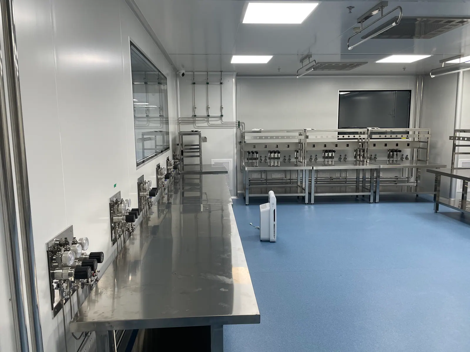
Biopharmaceutical Laboratory Gas Supply
Define gas utility boundaries for research, analytical quality control and process support with attention to use-point quality, monitoring and maintainable records.
APPLICATION OVERVIEW
Begin with the way this laboratory actually works
Biopharmaceutical facilities use gases for several distinct purposes. Analytical instruments may need a stable, clean carrier or support gas. Research spaces may need flexible nitrogen, carbon dioxide or instrument air. A gas that directly contacts a process stream or product can trigger a different quality and documentation discussion. A biopharmaceutical laboratory gas supply plan should therefore begin with the intended use of each gas at each point, not with a universal purity label or an assumed cleanroom standard. The source, distribution, monitoring and maintenance plan should reflect the use-point requirement.
This page focuses on facility and laboratory interfaces for research, development and quality-control settings. It does not assert that any installation is GMP qualified or that one component set satisfies every pharmaceutical process. A project team must establish applicable quality requirements, user requirements, approval roles and validation scope for its own operation. LGF Lab Gas Flow can help define the source-to-terminal hardware and records needed for a reviewable engineering scope.
01 / USE-POINT INTENT
Classify every gas by what it does at the use point
The same gas name can represent different quality needs. Nitrogen may serve an analytical instrument, a vessel headspace, a general laboratory purge or a process-contact operation. Record the function, expected flow, pressure, allowable contaminants, duration and consequence of a supply interruption for every terminal. Include the room, instrument or process skid owner, connection and any supplier or pharmacopeial requirement that the quality team has approved. Do not infer a gas grade from the word “biopharma.” The use-point schedule should explain why a particular quality limit applies and how it will be verified.
Separate research utility from controlled process utility where the consequences differ. One shared line can be economical, but it may make change control or monitoring difficult if some outlets have tighter requirements than others. Define which branches need local pressure indication, sampling access, filtration or additional control. ISPE’s process-gas guidance emphasizes determining quality properties from gas use; that is the right starting point for engineering, with the site quality group deciding how its own requirements are applied.
02 / SOURCE STRATEGY
Match source capacity and continuity to laboratory work
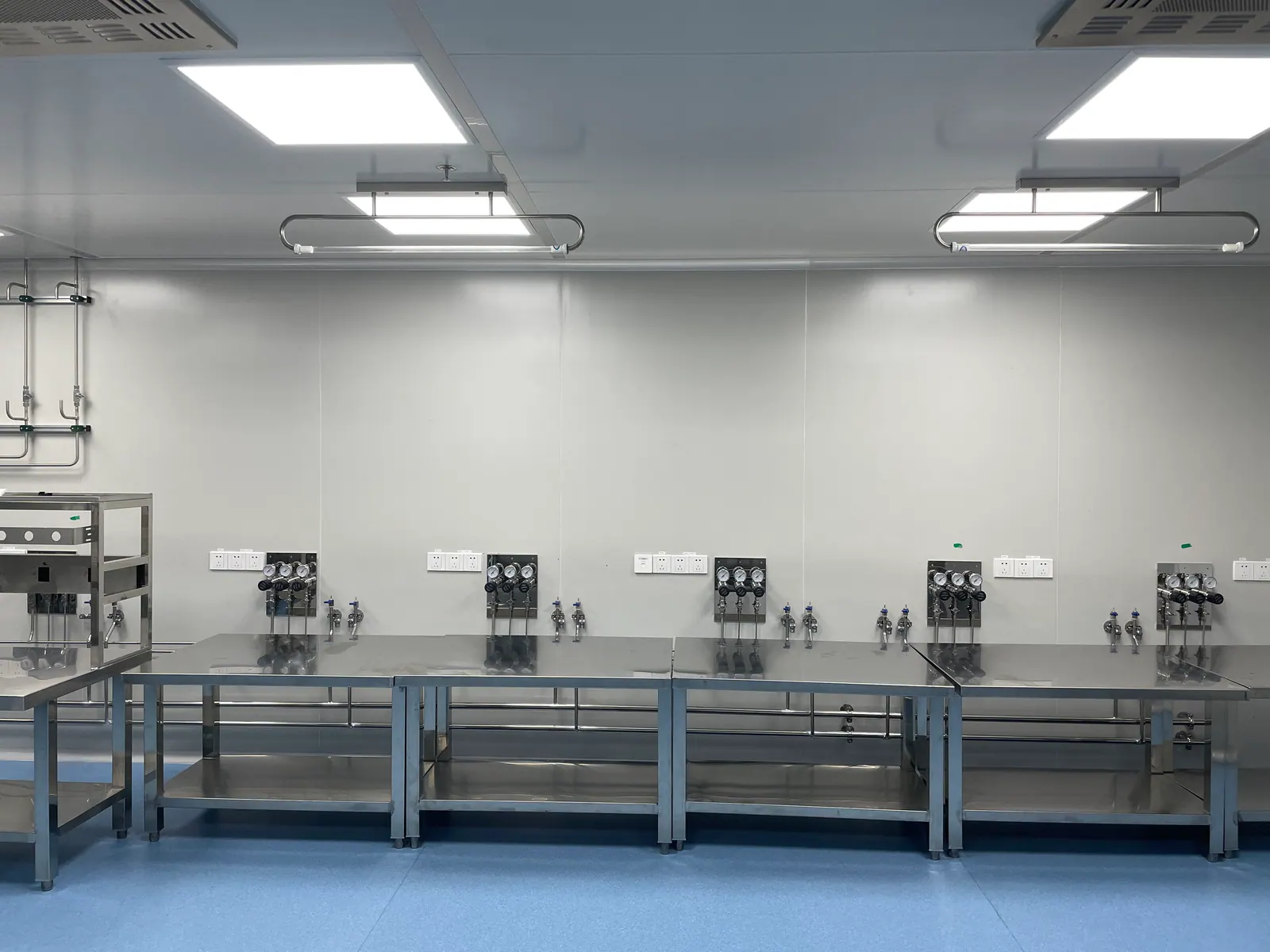
A source may be a cylinder bank, bulk supply or another approved utility arrangement. Select it from total demand, peak demand, continuity requirement, physical access and gas-quality risk. A laboratory gas manifold and changeover system can reduce interruptions when an analytical sequence or process-support operation cannot stop at an arbitrary cylinder change. Its reserve time, alarm indication and change procedure must still be defined. Document the upstream supplier boundary and what happens when a delivered cylinder or source package changes.
Source equipment should be accessible for routine changeout and maintenance without compromising the controlled working area. Identify pressure-control stages, isolation, filtration or purification where justified, and sampling points if the user requirements call for them. A source room can be physically separate from the laboratory, but it remains part of the quality and safety chain. A facility team should be able to identify which outlets depend on that source, how a fault is communicated and whether an alternate supply is permitted.
03 / DISTRIBUTION
Keep the clean utility route visible and serviceable
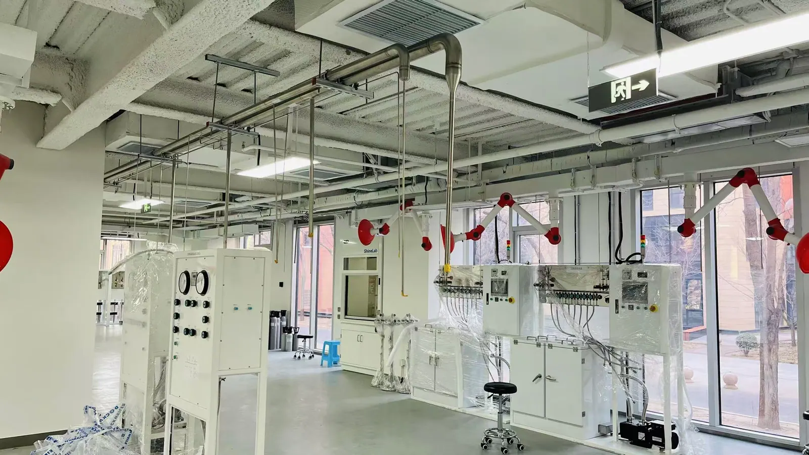
Map the full gas route from source to each point of use. Define pipe material, connection method, slope or drainage considerations if applicable to the service, branch isolation, identification and access for maintenance. The degree of surface finish or component cleaning should follow the agreed use-point quality and maintainability requirements. A high purity laboratory gas system needs more than a specification for tubing grade: fabrication, protection during construction, flushing or purge and post-maintenance restoration can influence the delivered condition.
Coordinate the utility path with cleanroom and laboratory layout, ceilings, service corridors and future equipment changes. Avoid inaccessible joints where a leak or contamination problem would be hard to investigate. Provide a branch arrangement that limits the impact of maintenance on unrelated work, with clear drawings and valve tags. When a clean utility crosses a room boundary, agree who owns the terminal connection and what work requires quality review. Do not route a new branch on the assumption that all laboratory gases share one approved contamination class.
04 / LOCAL CONTROL
Design terminals around actual instruments and operators
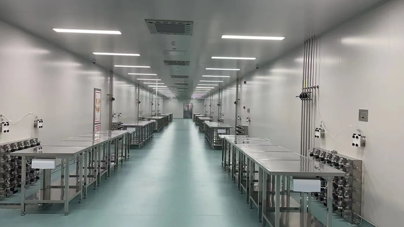
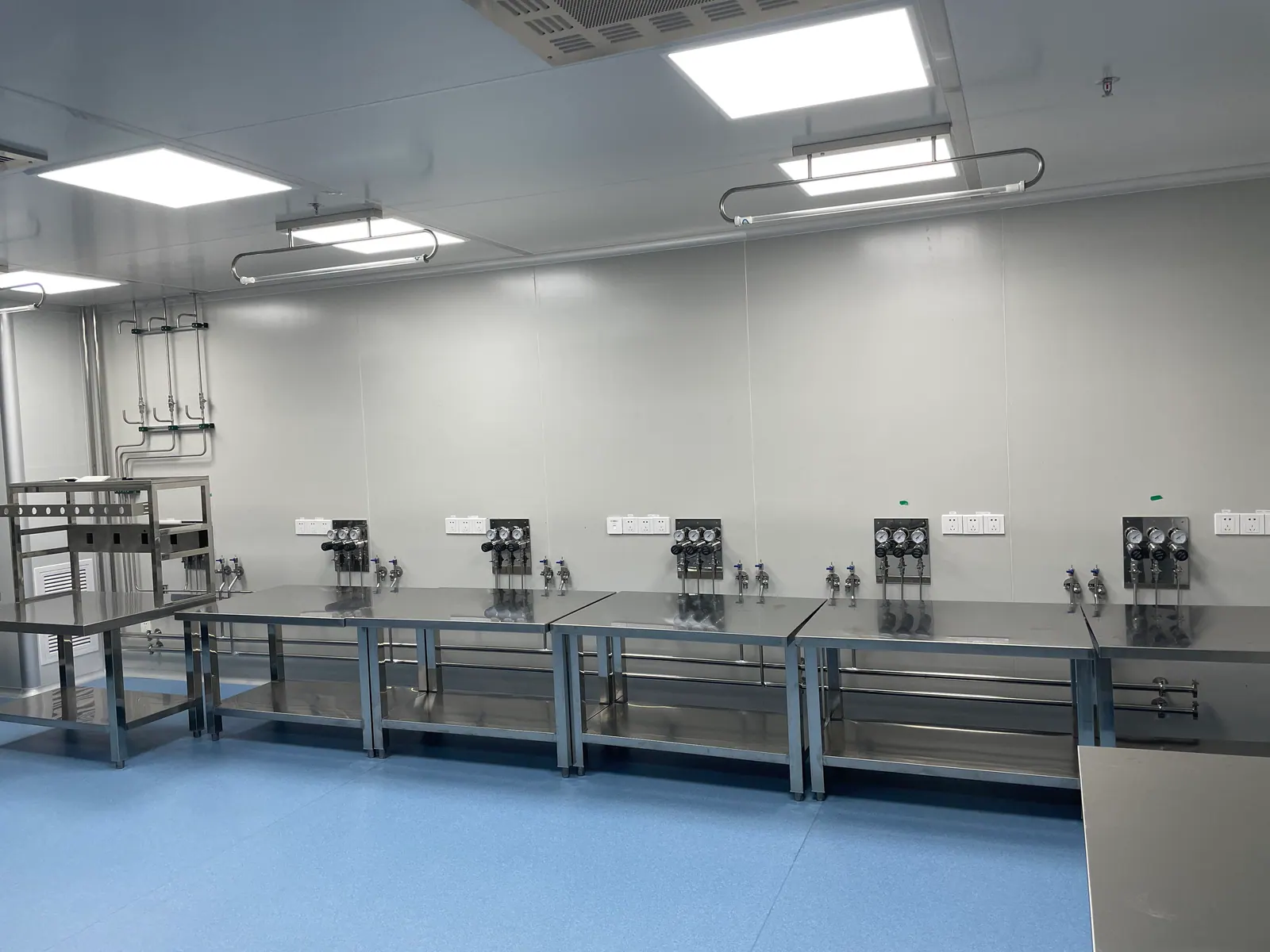
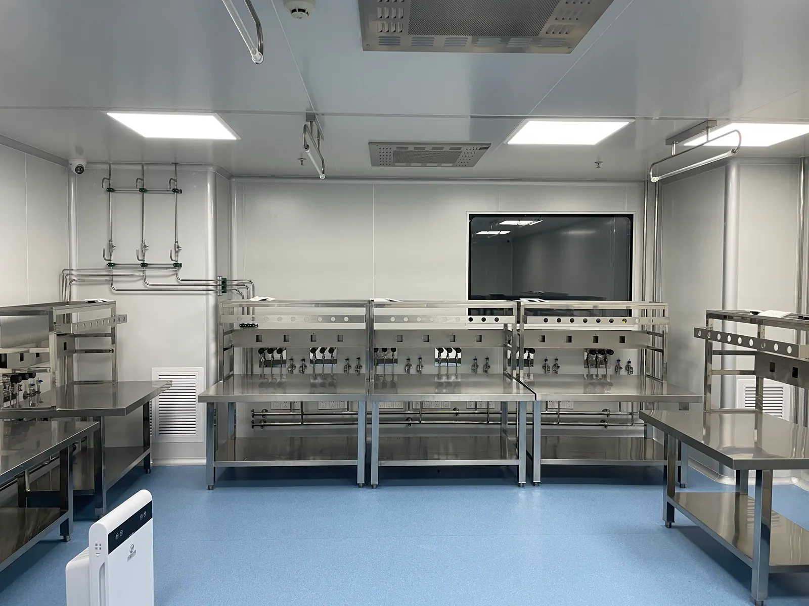
Point-of-use equipment can provide final pressure regulation, isolation and indication close to the consumer. Locate it where operators can read and reach it without interfering with sample handling or equipment access. Label gas, service range and the asset served. If a flexible connection is needed, specify and inspect it as part of the gas path rather than an untracked consumable. For sensitive analytical instruments, the manufacturer’s inlet purity and pressure requirements should be reflected in the terminal arrangement and the commissioning checks.
Where process use is involved, the utility and process skid interface must be explicit. Record the handoff connection, expected pressure variations, backflow considerations, required alarms and responsibility for final qualification. A gas panel should not be described as “validated” simply because it has clean components. The user’s approved requirements, test plan and quality-system procedures determine the evidence needed. Engineering should make those activities possible with accessible sample and test points where required.
05 / MONITORING
Make utility conditions and interventions reviewable
Monitoring should be chosen according to the risk of a quality or supply failure at each use point. Pressure indication and low-source alarms can help operations; contaminant monitoring or periodic sampling may be needed where the quality group requires it. Define who sees each alarm, the response time, the action and the record. A dashboard alone does not establish gas quality unless its sensors, locations, limits and calibration are appropriate. Distinguish process-critical monitoring from general facilities status so that operators understand the consequence of an alert.
Plan how cylinder changes, filter replacement, line opening and new equipment connections are recorded. A maintenance action may require a different restart check depending on the gas use. Document access rights, work permits or change-control triggers as the facility requires. The objective is not to create paperwork for every pressure reading; it is to make the conditions that could affect a test or process traceable and to prevent a utility repair from silently changing the validated boundary.
06 / ACCEPTANCE
Handover evidence should match approved user requirements
Develop a test matrix before installation. It may include material and component records, pressure and leak integrity, line identification, cleanliness or purge checks, alarm and changeover tests, calibration records and use-point verification. The exact qualification scope is a decision for the regulated facility. Keep construction acceptance, equipment commissioning and any quality qualification distinct so that each has a defined owner. Testing a main header at the source does not establish delivered quality at every terminal, and an analytical instrument startup does not prove the alarms and isolation work.
Provide as-built drawings, point-of-use schedules, component records and operation procedures in a form the maintenance team can keep current. Agree what evidence will be required after a branch modification or a source change. When requesting a quotation, include the approved gas-use schedule and quality expectations, not only a room plan. That allows a supplier to price the right regulators, valves, piping components and verification activities while making exclusions visible for quality-team review.
PLANNING IN PRACTICE
Decisions to resolve before the specification is fixed
User requirements
Write a user requirement for each gas use before selecting hardware. The document should state the process or analytical purpose, delivery pressure, flow, quality attributes, monitoring, continuity and what constitutes a failure. It should also identify who approves the requirement and who maintains it after handover. A phrase such as “clean nitrogen” is too vague for a supplier to build or for a quality team to verify. If a gas can contact product or a critical surface, the site’s quality specialists need to define that risk explicitly.
Translate the approved requirements into a traceable design and test matrix. The supplier can show how source selection, distribution, terminal components and records address each engineering requirement. This does not replace the facility’s own qualification process, but it prevents the eventual test package from being a collection of unrelated pressure records.
Contamination pathways
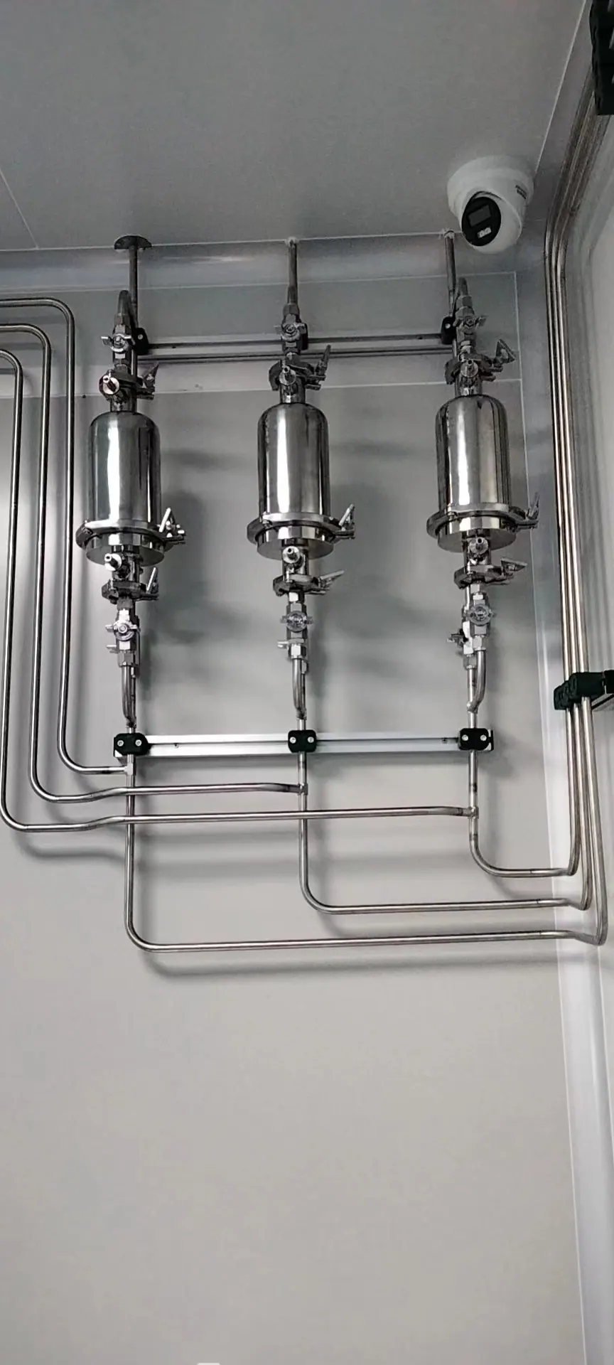
Consider how particles, oil, moisture and microorganisms could enter the line for the specific service. Their relevance differs by use point; not every research instrument needs the same controls as a process-contact utility. Review source generation or supply, storage, filtration, pipe material, joint method, drainage, dead legs and maintenance openings. The design should identify where an excursion could be detected and how affected outlets would be assessed. Avoid an unmeasurable claim that a line is “pharmaceutical grade” without a defined delivered specification.
Where periodic testing is planned, place sampling points where they represent the intended users and can be used safely. Specify what happens if a result fails: which branch is isolated, who evaluates impacted work and what must be checked before return to service. These operational questions can change the layout before installation.
Cleanroom interfaces
Route utility work so that routine servicing can occur without unnecessary entry into controlled areas where possible. Where a panel is inside a cleanroom, review its materials, accessibility and cleaning method with the room design team. A source outside the room can reduce disturbance at the bench, but every penetration, terminal and final hose still needs a defined responsibility. Coordinate with equipment placement and air handling before fixing outlets in a wall.
If a new analytical or process skid is expected later, plan a controlled connection point and adequate capacity. Keep it isolated and documented until an approved change. Do not call a capped live branch “future-proof” when nobody knows its gas class or test status. The next equipment project should be able to trace and verify it without relying on memory.
Continuity and deviation
An interrupted supply can have different consequences: a research run may restart, an analytical sequence may need investigation, or a process-support operation may need formal deviation handling. Classify these events at each use point. Then set reserve capacity, alarm routing and backup strategy accordingly. A single automatic changeover device cannot resolve every consequence. The system must make an interruption recognizable and provide evidence for what happened.
Agree who records alarms and who decides whether affected work can resume. Separate the facilities action to restore pressure from the quality decision about material or results. This division should appear in operating procedures and training. It reduces delays and prevents a hurried utility reset from concealing an event that matters to the regulated process.
Lifecycle review
A biopharma laboratory gas system will be maintained, expanded and inspected over many years. Build an asset register for regulators, filters, valves, gauges and sensors with their service intervals and calibration status where relevant. Keep spare-part compatibility and isolation requirements with the as-built drawing. When a component is replaced, assess whether the new part is equivalent for the approved service and whether return-to-service testing is needed.
Set a review trigger when a process, instrument, room classification or gas supplier changes. This is more useful than leaving a static qualification binder untouched. A controlled, current record helps engineering and quality teams decide whether a change remains inside the original design envelope or requires additional approval.
DESIGN REVIEW
Practical checks that protect the full gas path
Quality by use
Classify analytical, research, process-support and direct-contact duties separately. Each can have a different justified quality target and monitoring approach.
Source replacement
Record what is checked when a cylinder, bulk source or upstream supplier changes. A new package should not silently alter a controlled use-point condition.
Changeover need
Evaluate the cost of interruption and the monitoring of reserve capacity. Automatic changeover helps only if operators know when to replenish the spare source.
Maintenance boundary
Identify where facilities work ends and controlled-process review begins. A repair upstream of several critical outlets may require a wider return-to-service check.
Sampling access
If routine or event-driven gas-quality sampling is required, plan accessible locations and safe sample procedures before pipework is fixed.
Documentation
Make the gas-use schedule, route, valve list and test records consistent. A disconnected set of documents is difficult to use during a deviation or renovation.
Defined quality attributes
Specify quality in attributes the site can verify: for example pressure range, purity or named contaminant limits where relevant. The exact limits must come from approved user needs. A generic promise of “medical” or “pharma” quality is not enough to set component selection or acceptance tests.
Sampling representativeness
A source sample and a remote use-point sample answer different questions. If the quality strategy depends on sampling, design sample points that represent the affected outlets and are safe to use. Agree on purge volume and sample procedure so the method does not create the very contamination it is meant to detect.
Alarm classification
Classify low pressure, quality deviation and detector alarms by their operational consequence. The notification and response may differ between a research bench and a process-contact line. Keep alarm text specific enough that responders identify the source and affected use points quickly.
Return after maintenance
A regulator swap, filter change or branch opening can require a tailored return-to-service check. Define the check before the work begins and record completion. The maintenance team can restore the utility, while the site quality team decides whether affected process or test activity needs additional assessment.
Future audits
Maintain a traceable relationship between user requirements, design decisions, installed components and test records. A reviewer should be able to see why a given outlet has its quality class and which evidence supports it. This is more useful than a large unindexed binder that cannot be connected to the active system.
START THE PROJECT CONVERSATION
Start with the biopharma gas user requirements
A useful technical proposal starts with operating conditions and a clear division of responsibility. Send the information available today; unresolved items can become design-review questions.
- Gas uses and classified points of use approved by the site team
- Purity, pressure, flow and contaminant criteria for each application
- Source continuity and reserve-time requirements
- Room classifications and maintenance-access boundaries
- Monitoring, sampling, alarm and record expectations
- Construction, commissioning and qualification responsibilities
FREQUENT QUESTIONS
Questions to settle before equipment selection
Is every biopharma laboratory gas a GMP process gas?
No. Requirements depend on how the gas is used and the site’s quality system. The responsible team must classify each use point.
Can analytical and process-support gases share a line?
Only after compatible quality, pressure, risk and change-control needs are reviewed. Separate lines may simplify monitoring and maintenance boundaries.
Does a supplier panel make the utility validated?
No. Qualification depends on approved user requirements, installation, testing, records and site quality procedures.
Where should gas quality be checked?
At locations and intervals justified by the use-point risk and approved quality strategy. A cylinder certificate alone may not represent delivered gas after distribution.
TALK TO LGF Lab Gas Flow
Turn the gas-use schedule into a reviewable equipment scope.
Share the room plan, instrument list, gas requirements and building interfaces. We can help define source control, distribution and point-of-use equipment for your laboratory.