
APPLICATIONS / ADVANCED MATERIALS
Advanced Materials Research Laboratory Gas Supply
Gas delivery planned around changing process recipes, sensitive research equipment and the boundaries between source, reactor, monitoring and exhaust.
APPLICATION OVERVIEW
Begin with the way this laboratory actually works
Advanced materials research often tests small changes in chemistry, pressure, flow or process sequence. A gas line that is adequate for a general laboratory instrument can be unsuitable for a deposition reactor, surface-treatment tool or sensitive characterization method. Materials teams may use inert carrier gases, reactive precursors, hydrogen, oxidizers and specialty mixtures within the same facility. A useful advanced materials research laboratory gas supply design connects the experimental recipe to the gas source, clean delivery path, local control, hazard response and downstream exhaust. It also anticipates the next recipe without leaving uncontrolled spare connections.
This guide is for project managers and engineers planning research-scale equipment, not a recipe for a particular reactor. It emphasizes interfaces and design questions that should appear in a project scope. A specific MOCVD, ALD, CVD, etching or thermal-processing tool can have requirements that differ sharply from its neighbor. Obtain the tool-maker’s current gas schedule, site-preparation guide and interlock description. Qualified process and safety specialists must approve gas compatibility, cabinet and exhaust design, purge sequence and acceptance tests for the actual substances.
01 / PROCESS MAP
Translate each research recipe into a gas-service schedule
List every process gas and precursor, its composition, supplier package, concentration, source pressure, carrier flow, peak demand, purity and allowed contaminants. Map which tools use it, whether the gas can be shared and how a recipe changes the duty. A laboratory gas delivery system specified only by cylinder count and nominal pipe size cannot show what happens when two reactors demand the same carrier gas or when a new tool introduces a different chemistry. Mark development services separately from established tools so that a trial gas does not quietly become a permanent branch on a common header.
The schedule should distinguish continuous utility flow, short process pulses, chamber purge and emergency purge. Those duties can create very different pressure and capacity requirements. Specify what the tool expects at its inlet and where mass-flow control occurs. If the tool includes its own gas box, define precisely where the building system ends. The interface list should identify connection type, pressure envelope, alarm contacts, emergency isolation, exhaust conditions and responsibility for final verification. This avoids duplicate controls and gaps between the facility contractor and equipment supplier.
02 / GAS SOURCE
Select containment and handling for the actual hazard
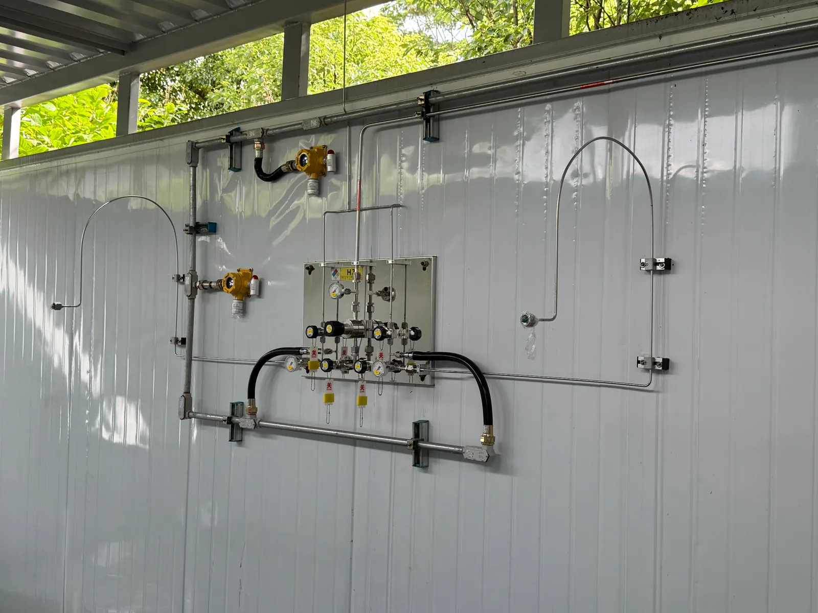
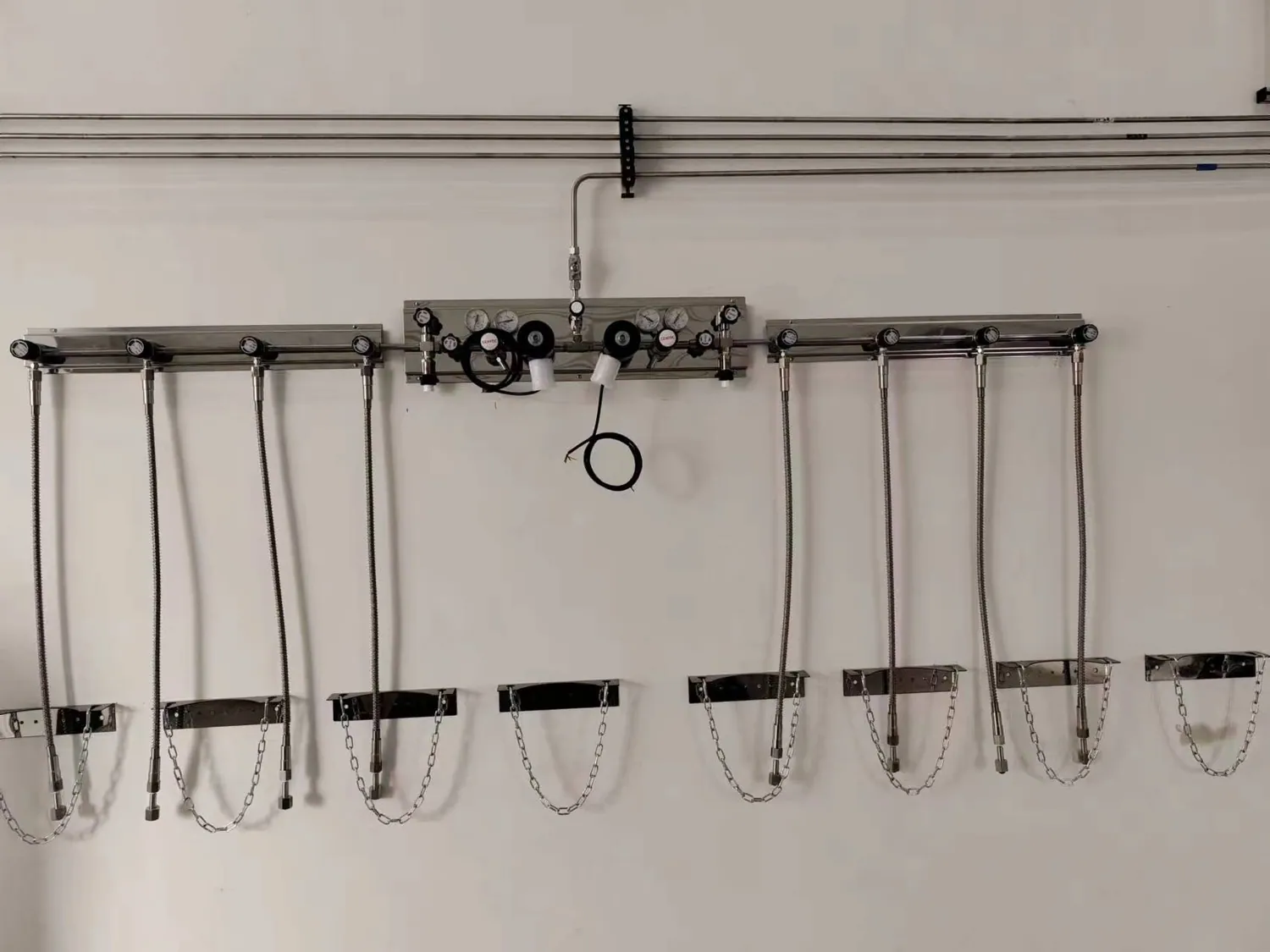
Some materials gases can be supplied from a managed inert-gas bank. Others require a dedicated enclosure, compatible regulator, purge arrangement and reviewed exhaust. The right choice depends on the named substance and inventory, not on a generic label such as “specialty gas.” Consider cylinder change frequency, access, segregation of incompatible gases and how a leak would be detected and contained. A gas cabinet should be assessed with its exhaust, isolation and monitoring interfaces; a metal cabinet alone is not a safety system. Confirm local approval, fire and building requirements before selecting the source package.
For high-purity applications, trace oxygen or moisture introduced at cylinder change can affect a process even if the cylinder grade is correct. Select UHP gas regulators, diaphragm valves and fittings for cleanliness, pressure, materials and purge capability in the context of the actual gas. Define the expected endpoint quality and a practical way to check it. Some precursor packages and corrosive services need equipment and procedures beyond a conventional inert-gas regulator train. Preserve a clear, serviceable source layout so that operators can identify the active package, isolation state and safe maintenance boundary.
03 / CLEAN PATH
Design the distribution path as part of the process
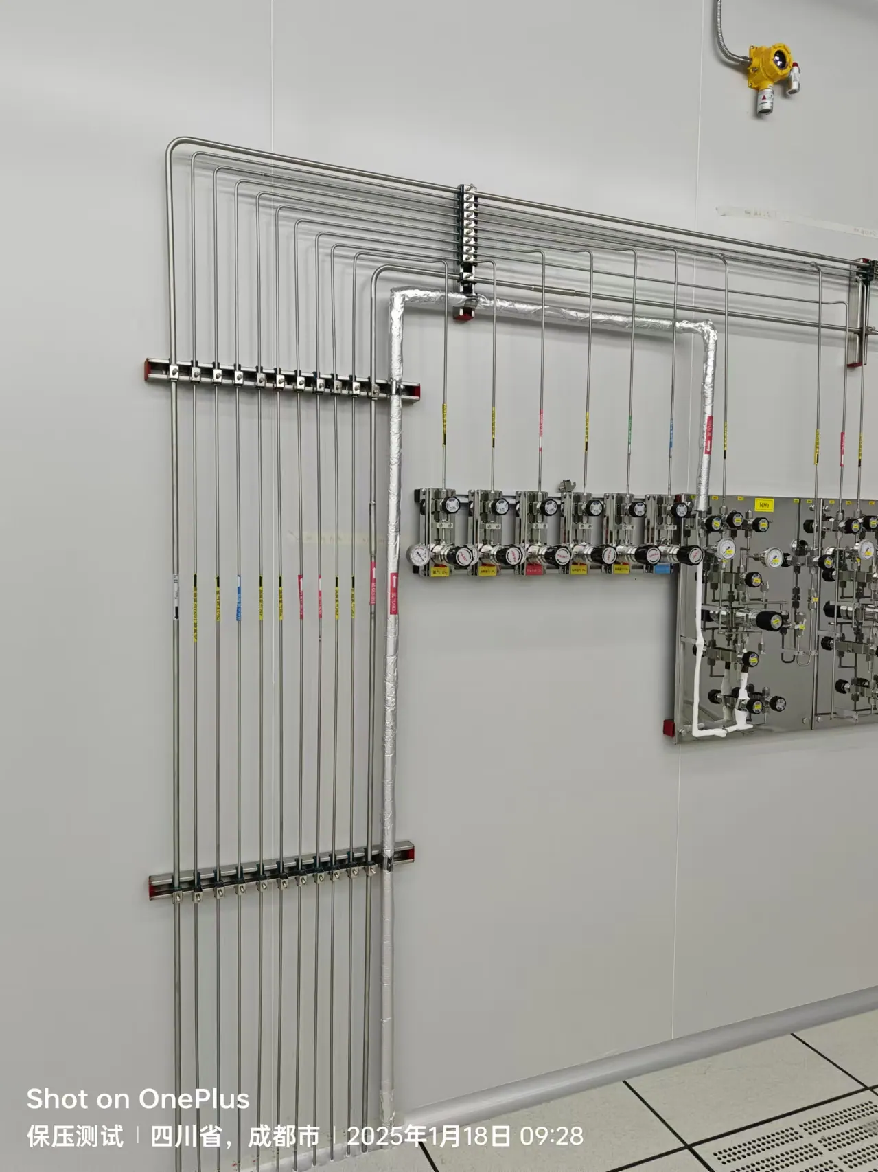
Route high-purity laboratory gas lines to minimize avoidable joints, stagnant sections and contamination during installation. Record tubing material, internal finish where required, joining method, cleaning, cap removal and the acceptance method. A long branch serving several tools can have a different dynamic response and larger purge volume than a short dedicated run. Calculate pressure loss under the actual simultaneous and pulsed duties. The line should remain accessible for inspection where possible, with labeled isolation points and a drawing that maps each gas all the way to the equipment interface.
Do not assume that “316L stainless steel” alone defines a high-purity result. Connection design, valves, seals, fabrication practice, testing and later maintenance all affect the delivered gas. When two tools need the same nominal gas but different contamination limits, evaluate whether they can share a source or require separate purification and distribution. A research project may also outgrow its initial flow estimate. Identify which source and branches can expand without compromising existing tools, and document the capacity assumptions before future additions are approved.
04 / TOOL INTERFACE
Coordinate pressure control, interlocks and emergency states
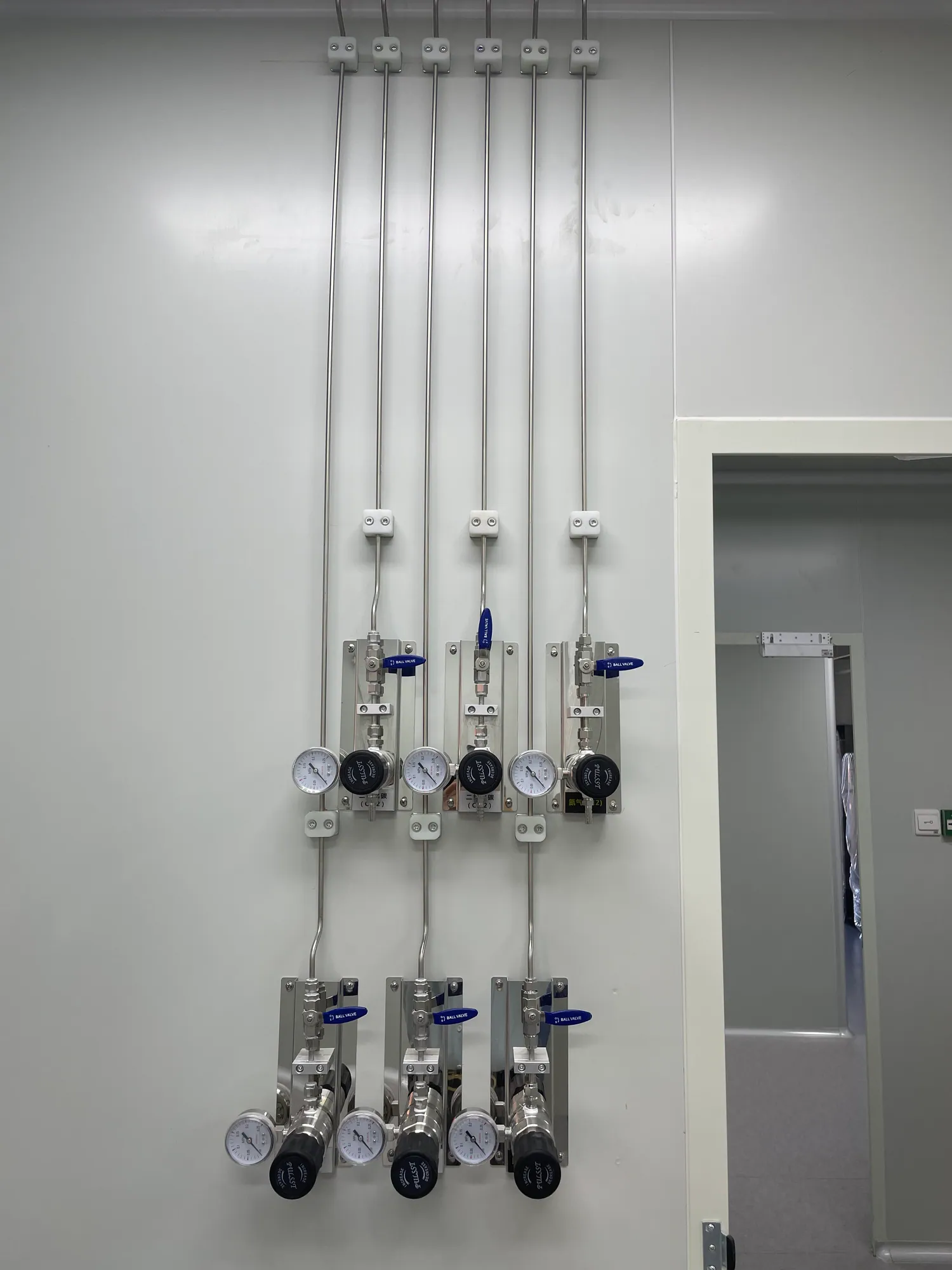
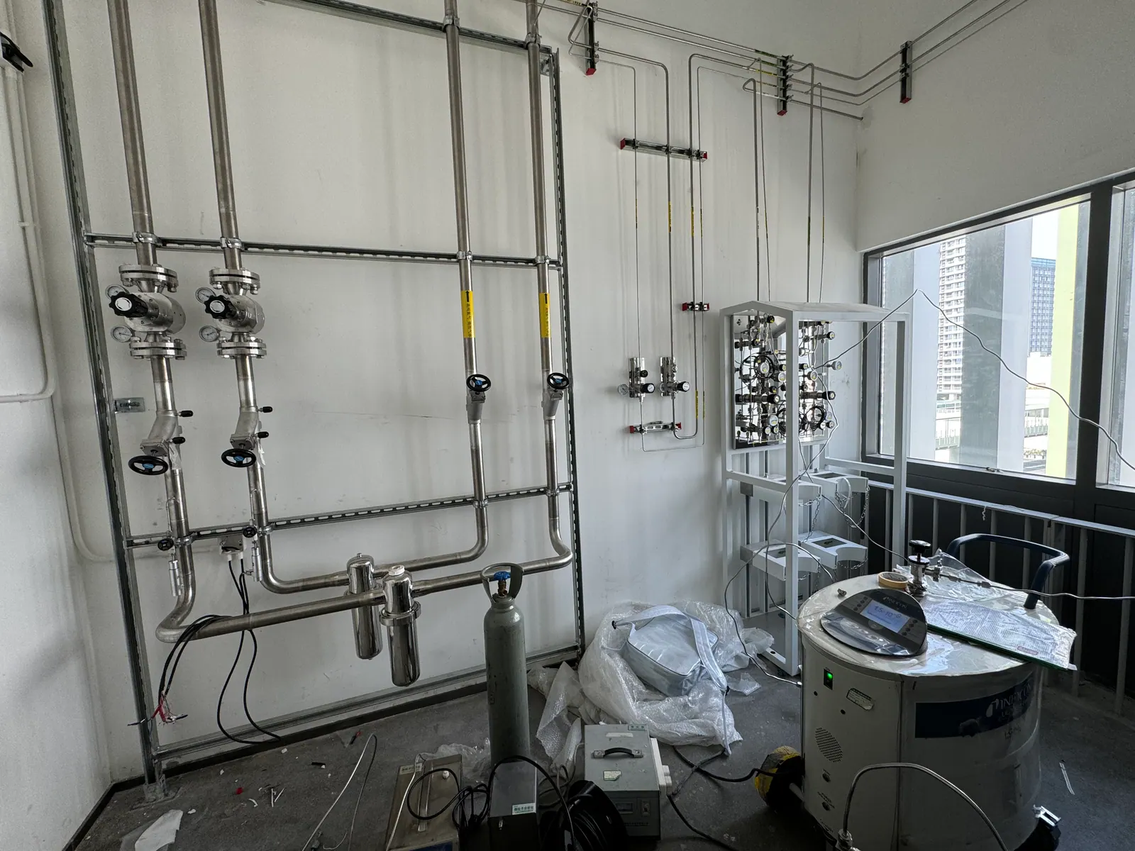
The equipment inlet is a handoff point between facility and tool. Agree normal pressure, maximum allowable pressure, transient behavior, flow and permitted connection before fabrication. If both the facility panel and tool control pressure, their settings and relief approach must be reviewed together. A local point-of-use panel may provide readable pressure and isolation, but its valve positions must be reflected in the tool startup and shutdown procedure. For multiple process lines, label the panel by gas and tool rather than by an ambiguous room number alone.
Document what each interlock does during loss of exhaust, detector alarm, power failure or emergency stop. Which valve closes? Does a purge continue? Who may reset the system? These are design questions for the full installation, not features to infer from a controller brochure. Stanford’s published MOCVD procedure illustrates the importance of checking gas-leak monitoring before operation; the site-specific control sequence must still be engineered and tested for the local tool and gases. Do not treat an alarm display as evidence that gas has been isolated.
05 / PURGE & EXHAUST
Close the loop between source, chamber and discharge
A materials process can send unreacted gas, purge flow or reaction by-products toward an exhaust or abatement system. Define the expected discharge composition and flow for normal operation, process transitions and credible faults. The tool maker, mechanical engineer and safety reviewer need a shared boundary drawing from cabinet vent to final discharge. A supply-side purge step is not automatically an appropriate treatment method for an exhausted process gas. Keep purge purpose, purge gas quality, vent destination and acceptable completion criteria explicit in the procedure.
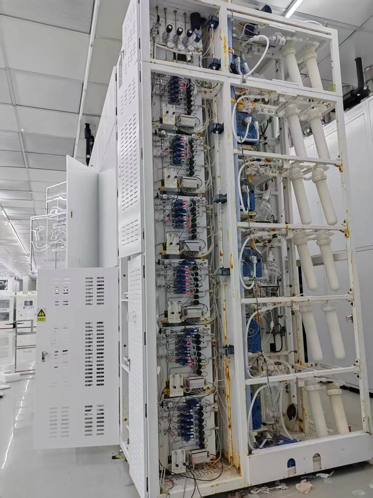
Arrange maintenance isolation so that a technician can work on a source or tool without ambiguity about trapped gas. Where a line is opened, document cleaning, purge and restart checks. A system that works for a commissioning demonstration may be difficult to maintain after several recipe changes if the valves and exhaust connections are inaccessible. The layout should support safe changeout and testing without forcing operators to improvise a hose or bypass. See the linked purge and exhaust solution for broader interface planning.
06 / CHANGE CONTROL
Commission for recipe changes and research turnover
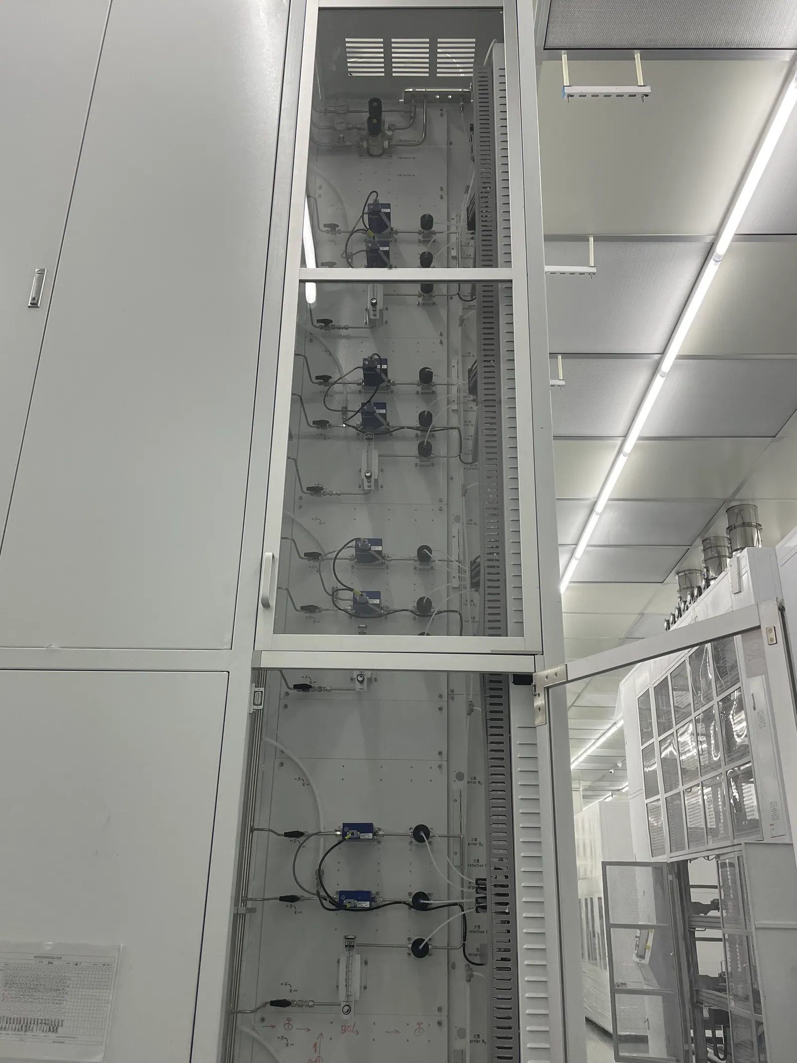
Acceptance should verify line identity, component records, leak integrity, specified cleanliness checks, regulator range, alarm logic, isolation and the tool interface. Witness the conditions that matter to the process: simultaneous demand, recipe transitions and start-up after a source change. Record the as-built route and control cause-and-effect matrix. A successful reactor run is valuable but does not by itself establish that every alarm, spare branch or maintenance path behaves correctly. Keep a punch list for interfaces that the equipment and facility contractors must close together.
Research teams change gases as experiments evolve. Require a review before substituting a cylinder grade, precursor or mixture or connecting a new tool to an existing header. Reassess material compatibility, hazard controls, capacity, exhaust and decommissioning. The line register should identify unused branches and their isolation state. A maintainable high-purity laboratory gas system lets the next researcher see the basis of the original design and understand what must be checked before a new process begins.
PLANNING IN PRACTICE
Decisions to resolve before the specification is fixed
Process change review
A new recipe may alter gas concentration, flow, purge duration or by-product composition even when the tool hardware is unchanged. Require a review of the source package, regulator, valve train, detector coverage, exhaust and disposal route before the recipe is released for routine use. Small research batches do not automatically mean small hazard consequences. Document which changes stay within the original approved envelope and which require engineering work. This makes experimentation possible without losing control of the shared facility infrastructure.
A change form should identify the substances and the exact equipment path, not simply say “new specialty gas.” The process owner can explain experimental intent; the gas-system engineer can check delivery capacity and compatibility; the safety team can review release and response scenarios. Preserve that decision in the as-built package so the next researcher knows why a branch was configured as it was.
Purity budget
For sensitive deposition or surface work, assign a contamination budget to the full source-to-chamber path. Identify what the source certificate covers, where ambient ingress could occur and how a line will be checked after installation or maintenance. A high-purity cylinder grade is one part of the budget. A regulator with unsuitable wetted materials, an uncapped tube during construction or an excessive stagnant section can defeat the intended condition. Avoid claiming a purity number at the tool without a corresponding measurement or justified verification method.
If different tools have different purity demands, a shared source may still work when downstream treatment and isolation are defined. The choice depends on flow, response time, maintenance and the impact of a single fault. Compare dedicated and shared paths using the actual recipe envelope and service plan, not only pipe length.
Emergency behavior
Describe abnormal states in a cause-and-effect table: detector alarm, cabinet exhaust loss, tool emergency stop, power interruption, pressure excursion and maintenance isolation. For each, state which valve moves, whether purge starts or stops, where residual gas can go and who is authorized to reset. A control system can only be accepted when those actions are tested at the facility and tool boundary. An emergency stop that closes the source while trapping a hazardous section may require additional engineering review.
Walk the sequence with the equipment supplier and the facility operator before final wiring. They may use the same signal name for different actions. Test the system in safe simulated conditions and record the results. Clear behavior reduces the temptation to bypass an interlock during a research run and supports later troubleshooting.
Cylinder and precursor replacement
Source changes can be a high-risk and high-contamination activity. Define access, personal protection, isolation, purge, disconnect, new-package verification and restart in a site-approved procedure. The sequence must suit the actual gas and package; do not import a procedure from an inert-gas line to a reactive or toxic service. Provide gauges and valves where operators can see the state they are changing. Maintenance access, lighting and space should be considered during layout, not after the cabinet is delivered.
Record the change, source identity and any post-change check required by the research process. If a tool is sensitive to an initial transient, account for that in the restart plan. A designed source train and an executable operating procedure are complementary parts of the same system.
Decommissioning
Research tools eventually move or retire. Define how each line is isolated, purged, verified and marked out of service. A former precursor branch should never be treated as a general spare connection without a compatibility and cleanliness review. Update drawings and control logic when a tool is removed so alarms do not remain unexplained or become permanently bypassed. Trapped volumes and disconnected exhaust interfaces deserve a specific closeout check.
A good decommissioning record protects future projects. It tells a new team which pipe is available, what it previously carried and what evidence is needed before reuse. This is especially valuable in advanced materials facilities where the next process may differ more than the physical room layout suggests.
DESIGN REVIEW
Practical checks that protect the full gas path
Recipe-driven demand
Use the process recipe and tool manual to identify steady, pulsed and purge flows. A nameplate value alone may understate simultaneous supply or oversize a branch that normally runs at trace flow.
Shared carrier gases
A common inert-gas header can simplify supply, but cross-effects between tools and pressure drops during simultaneous operation must be tested. Reserve capacity and local pressure control should match the tool schedule.
Hazard review
Identify each substance and credible release location before selecting detectors, cabinets or automatic isolation. Detection technology and alarm threshold require a project-specific safety review.
Clean fabrication
Keep components protected until installation and define the cleaning, leak test and purge procedure before pipework is opened. A clean cylinder cannot repair contamination introduced during assembly.
Tool-provider interface
Write down the division of work for inlet fitting, control contacts, exhaust connection and start-up tests. Unassigned boundaries are a common source of late changes.
Future tool moves
A reserved branch is useful only when its gas identity, pressure and isolation are controlled. Reassess it before changing service; do not treat any unused valve as a universal connection.
Pressure transients
A process tool may draw gas in pulses rather than steadily. Check regulator response and line volume against that pattern. A stable static pressure reading can conceal a transient outside the tool’s permitted inlet range. Witness representative recipes when accepting a shared source or a long distribution route.
Incompatible services
Review gas segregation at the source, manifold, service chase and tool. Similar-looking stainless lines can carry substances that require very different purge and emergency handling. Label each valve and test port with the gas identity and direction of flow. Prevent field modifications that connect incompatible branches simply because fittings match.
Detector maintenance
A gas detector is only useful if its sensing technology, location, calibration and alarm interface remain appropriate to the current chemistry. When a tool changes gas or room layout, revisit coverage. Record test results and any bypass state; an unreviewed bypass can turn a designed protective layer into a false assurance.
Exhaust capacity
Compare normal process exhaust, purge peaks and fault scenarios against the mechanical system’s design envelope. An abatement device may have its own flow and composition limits. Record responsibility for monitoring the exhaust interface and the response when it falls outside the agreed operating range.
Service spares
Identify regulators, valves, seals and sensors that can be replaced without changing the approved gas path. Keep compatible spares and installation instructions available. A last-minute substitution after a failed component can alter wetted materials or control response at a sensitive research tool.
START THE PROJECT CONVERSATION
Inputs for a materials-research gas review
A useful technical proposal starts with operating conditions and a clear division of responsibility. Send the information available today; unresolved items can become design-review questions.
- Process and tool list with current manufacturer gas schedules
- Gas and precursor inventory, purity and contamination limits
- Steady, pulsed and purge flow, plus concurrent use assumptions
- Source package, room plan, cabinet and cylinder-change constraints
- Tool interlocks, detection and exhaust or abatement interfaces
- Planned recipe changes and future tools
FREQUENT QUESTIONS
Questions to settle before equipment selection
Can one high-purity header serve every research tool?
Only if gas grade, pressure, flow, contamination limit and operational interactions are compatible. Some tools need a dedicated path or local purification.
What makes a materials-gas line “high purity”?
It is the delivered condition at the tool, supported by a compatible source, clean components, fabrication, operation and an agreed acceptance method. The label alone is insufficient.
When is a gas cabinet needed?
That depends on the named gas, inventory, local rules and hazard analysis. The enclosure must be reviewed with ventilation, detection, isolation and maintenance.
How should a new precursor be introduced?
Treat it as a controlled change. Recheck compatibility, gas train, exhaust, monitoring, purge and the tool-provider interface before connecting it.
TALK TO LGF Lab Gas Flow
Turn the gas-use schedule into a reviewable equipment scope.
Share the room plan, instrument list, gas requirements and building interfaces. We can help define source control, distribution and point-of-use equipment for your laboratory.