
APPLICATIONS / THIRD-PARTY TESTING
Independent Testing Laboratory Gas Supply
Plan dependable gas delivery for a busy testing laboratory serving multiple clients, methods and instruments without losing traceability at the point of use.
APPLICATION OVERVIEW
Begin with the way this laboratory actually works
An independent testing laboratory earns trust through repeatable methods, documented equipment conditions and dependable turnaround. Its laboratory gas supply has a practical role in that work: deliver the gas, pressure and purity required by each analytical method while making source changes and maintenance visible to the people who use the instruments. The system must support a changing sample queue and a mixed fleet of instruments without allowing a convenient shared line to blur the requirements of one method into another.
This page focuses on the operating model of a third-party or contract testing facility. It covers multi-instrument capacity, calibration and reference gases, service continuity, change control and evidence for internal quality review. It does not replace instrument manuals, laboratory accreditation requirements or an engineering hazard assessment. The separate environmental monitoring application page deals with environmental sample workflows and their particular analytical techniques; the issue here is how a service laboratory controls utilities across many clients and methods.
01 / METHOD MATRIX
Build the utility schedule from active test methods
List every instrument and method that uses gas, then record its gas grade, connection, inlet pressure, flow, maximum run duration and whether a pressure interruption invalidates an analysis. Include calibration gas and reference standard use, not just carrier or plasma supply. A single room can host GC, GC-MS, ICP, atomic absorption, TOC and other devices with dissimilar needs. Some consume gas steadily; others have short high-demand cycles. Ask the instrument supplier for the current installation guide and record the exact model and configuration. Avoid selecting the manifold from an averaged laboratory demand figure that hides simultaneous peaks.
Connect each requirement to a responsible user and a controlled outlet. A method transferred to a new instrument, or a gas changed for a new detector, may alter the acceptable materials and pressure range. The gas schedule should be revision-controlled alongside the equipment list, with a clear route for approving a new connection. This creates a defensible boundary between facility utility maintenance and method ownership. A laboratory gas utility engineering company can use that schedule to design supply hardware, but it cannot infer analytical acceptance criteria from the pipe diameter alone.
02 / CONTINUITY
Plan cylinder change without interrupting critical runs
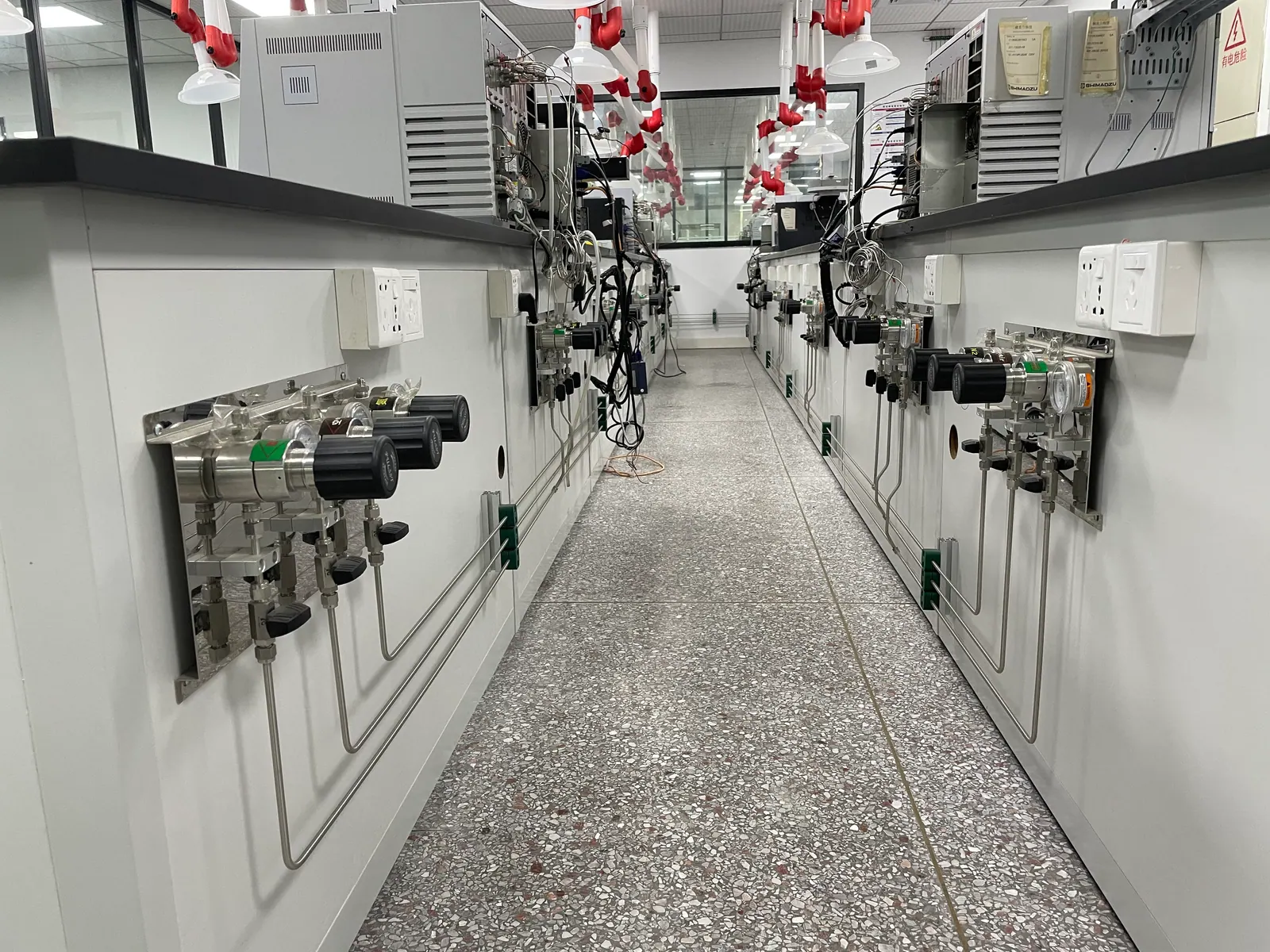
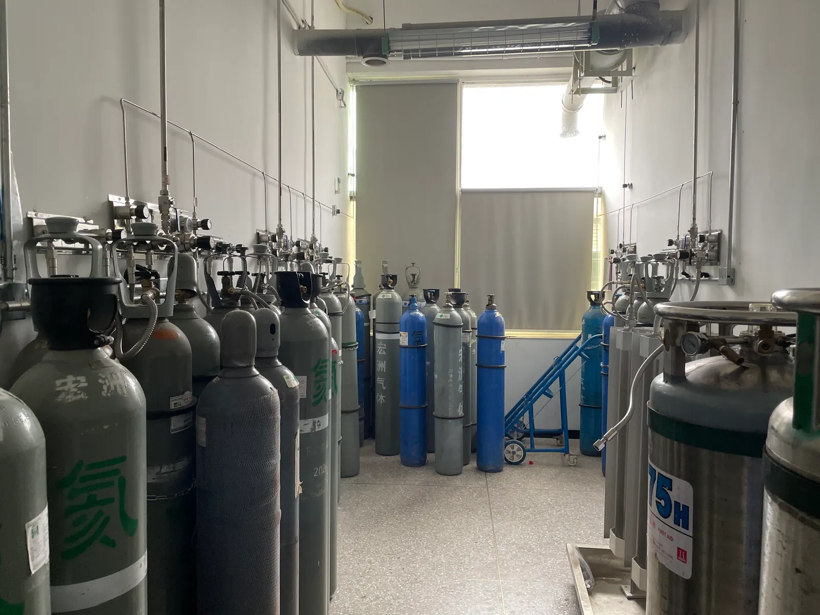
Testing revenue and client delivery dates can depend on long analytical sequences finishing without a gas interruption. Identify instruments for which a depleted cylinder stops work or requires a full method restart. A dual-bank gas manifold and changeover system may protect those lines, provided the changeover pressure, available reserve and alarm response are matched to actual use. A changeover mechanism does not eliminate failure if both banks are empty, the spare valve is closed or the operator never sees the low-pressure indication. Document those cases and the action expected from each shift.
Estimate source capacity from measured or manufacturer-stated consumption, operating hours and the number of simultaneous instruments. Include supplier lead time and the facility’s practical cylinder-storage limit. Where a long route is proposed, calculate pressure loss to the farthest point under peak demand. Divide branches so that one instrument can be maintained without shutting down all instruments that share a header. A source design should make routine bottle change and emergency isolation safe and legible, rather than put all continuity in one automatic component.
03 / QUALITY
Protect sensitive methods from avoidable contamination
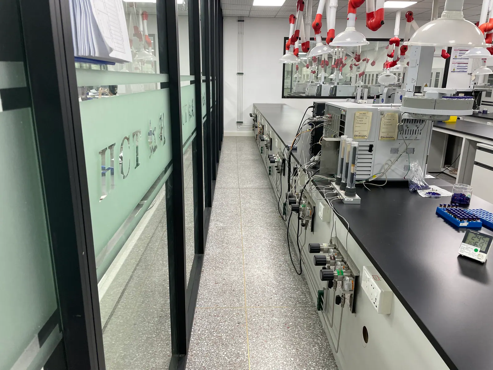
Delivered gas quality is determined by the entire path from cylinder valve to instrument inlet. Moisture, oxygen or hydrocarbon ingress may affect chromatographic baseline, detector sensitivity or trace measurements. Define the purity and contaminant limits from each method and instrument guide; then specify appropriate UHP high purity gas regulators, clean valves, tubing, connections and any point-of-use purification needed. A high-grade cylinder cannot correct an unsuitable downstream line. Conversely, not every support gas needs the most expensive ultra-high-purity hardware. Segment the utility classes according to measurable method needs.
The installation and maintenance process must protect that specification. Keep clean components capped until use, control pipe joining and leak-test media, and define how a branch is purged after opening. Document which tests establish pressure integrity and which establish cleanliness or delivered quality. Avoid claiming a generic pressure test proves suitability for trace analysis. Where sample results depend on a calibration mixture, treat its traceability, cylinder connection and expiry controls as method matters. The gas system should make that controlled use possible without implying it certifies the reference material.
04 / POINT OF USE
Make each instrument connection easy to identify and isolate
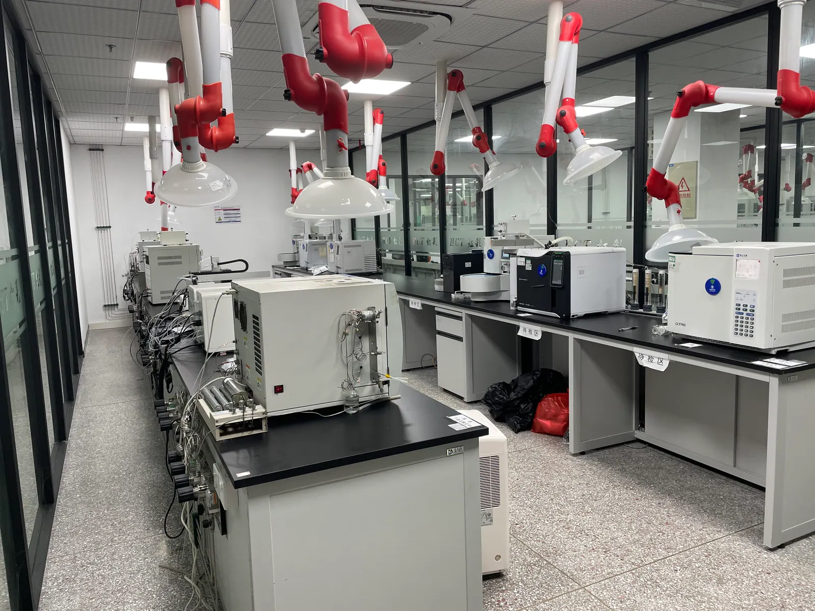
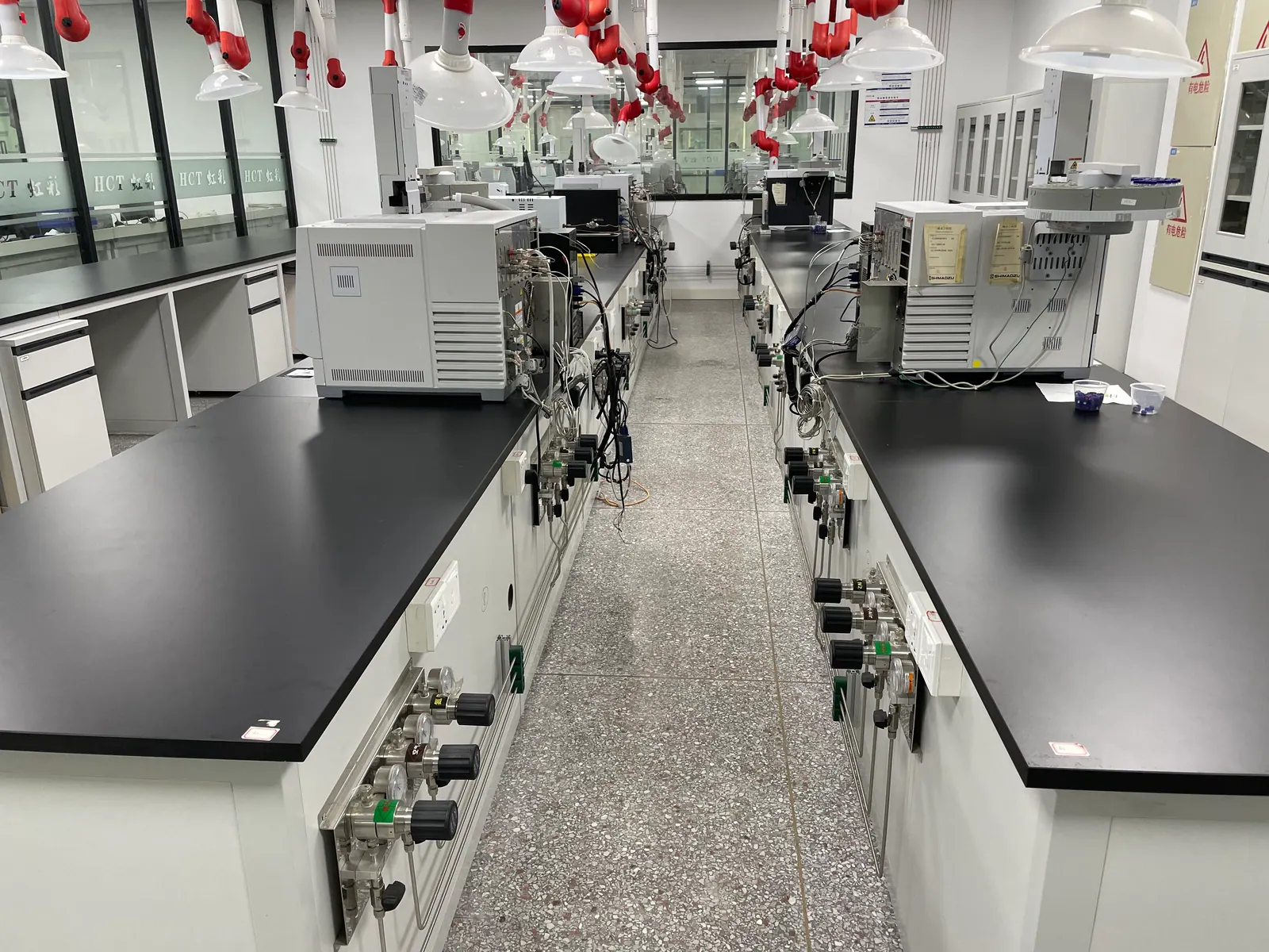
A compact point-of-use panel can provide local pressure indication, regulation and isolation for an analytical workstation. Its label should state gas identity, pressure range and the instrument or service it supports. This prevents a technician from adjusting a common source regulator to satisfy one instrument at the expense of another. If one branch serves several devices, show that relationship on the outlet schedule and set a maintenance procedure for the entire affected group. Flexible leads should be selected and inspected for the named gas, pressure and location; they should not be treated as an unrecorded extension of permanent piping.
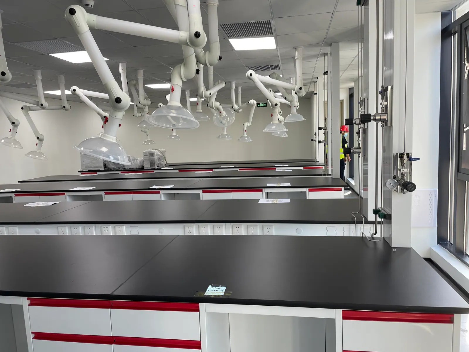
Locate terminals where operators can read them without moving equipment or reaching into a hazardous area. Leave access for filters, regulator maintenance and controlled disconnection. The working bench is often rearranged faster than building utilities can be modified, so coordinate future equipment slots without leaving unidentified live branches. For a laboratory with multiple shifts, a clear physical layout helps the next analyst recognize an abnormal indication before a batch of samples is lost.
05 / QUALITY RECORDS
Treat changes and alarms as reviewable events
A third-party testing laboratory needs to reconstruct equipment conditions when a result is questioned. The gas utility record should therefore identify source batches where relevant, cylinder changes, pressure alarms, maintenance work and any temporary bypass or instrument reconnection. The required depth of traceability depends on the laboratory’s methods and quality system; the utility design should provide useful indications and an accessible log rather than promise automatic accreditation. If data are sent to a building system, specify time stamps, alarm recipients and who reviews exceptions.
Control changes to gas grade, pressure range, materials and line routing. A small modification can affect several methods when a shared header is involved. Before returning a branch to service, verify its new label, leak integrity and instrument acceptance. Define who is allowed to reset an alarm or replace a regulator. This keeps the laboratory gas delivery system aligned with method control while preserving a practical maintenance path for facilities staff.
06 / COMMISSIONING
Verify the system during real operating conditions
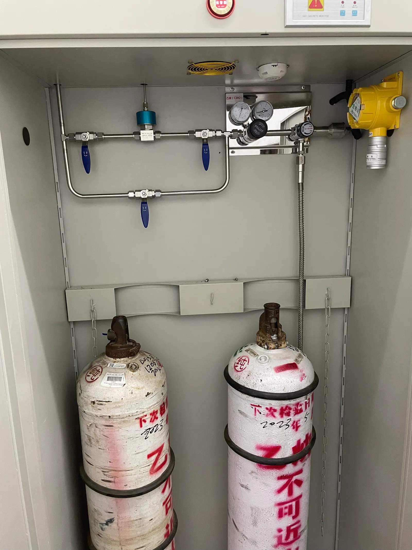
A useful commissioning plan checks each source and terminal in the same order that operators will use them. Record gas identity, isolation, set pressure, leak and pressure-test results, alarm operation, changeover function and the actual instrument inlet condition under concurrent demand. Manufacturer acceptance steps belong to the instrument owner. A line that holds pressure overnight may still fall below a required inlet pressure when several analyzers run together; a stable regulator may still allow contamination after poor cylinder-change practice. Keep those separate risks in the test plan.
Handover should include an outlet register, gas-route drawings, component records, approved cylinder-change steps, spare-parts list and a process for onboarding new instruments. Compare bids against the same point-of-use count, expected peak flow and testing scope. A cheap laboratory gas manifold system price can omit the very evidence and branch isolation a testing facility needs. The best scope makes the cost of uptime, quality control and maintainability visible before purchase.
PLANNING IN PRACTICE
Decisions to resolve before the specification is fixed
Client and method variability
A contract laboratory may change its analytical portfolio more often than a dedicated in-house lab. New client matrices can require a detector, calibration gas or method modification that changes utility demand. Create a change gate that asks whether the existing outlet has the right gas, pressure, flow and contamination limit. The review should happen before the lab commits to a turnaround time for the new method. A spare bench position is not automatically a spare gas service.
Link each outlet to a current instrument and method group, but keep the facility drawing understandable after equipment moves. Use durable labels and a controlled revision of the utility schedule. If analysts move a GC between benches, recheck the final connection and inlet condition at the new location. This avoids an apparent instrument problem that is actually a different branch pressure or a contaminated flexible line.
Measurement investigation
When an analytical result drifts, the gas path is one possible cause among many. A useful gas-system record lets the laboratory check whether source pressure changed, a cylinder was replaced, a filter was serviced or another instrument began using the header. Log these events with enough time resolution to compare them with method runs. Do not promise that pressure data alone explain a failed result; the purpose is to narrow the investigation. Where delivered gas quality is critical, agree on a sampling or verification method that the laboratory can repeat.
Preserve source and branch identity in the record. A multi-bank manifold can make supply continuous while obscuring exactly when the active bank changed unless that indication is captured. Maintenance staff and method owners should agree what events trigger a suitability check. A controlled investigation is faster than repeatedly replacing instrument parts without considering the utility.
Connection discipline
Several instruments may use visually similar fittings but need different gases or pressure ranges. Avoid a layout that invites casual hose swapping between terminals. Give each line a clear service label, select appropriate connections and make the permitted temporary arrangements explicit. A reference-gas cylinder used briefly for calibration should not be left connected to a routine utility outlet because it happened to fit. The laboratory’s method owner should approve temporary connections and document their removal.
Inspect final hoses and fittings as part of planned maintenance. They are often the most frequently disturbed section of an otherwise fixed distribution system. A pinched hose, loose fitting or unprotected adapter can defeat careful source and pipework design. Provide enough working clearance that analysts do not have to move heavy equipment to read a regulator or isolate the line.
Commercial scope
A quote for a testing laboratory needs a defined utility schedule, count of distinct gas services, estimated peak demand and acceptance criteria. Ask for separate pricing for source arrangement, distribution, instrument terminals, alarm integration and commissioning. This makes it possible to compare an automatic changeover option against a simpler source with a robust manual procedure. It also reveals whether the proposed system includes the delivery verification required by sensitive methods.
A cheaper proposal may assume a different gas grade, omit a branch or stop its scope at the room wall. Conversely, a proposal with every premium component may not improve an instrument that has modest requirements. Evaluate each material and control choice against the method matrix and interruption risk. This produces a more useful procurement decision than choosing on total price alone.
Operational readiness
Train both day and night staff on low-reserve indications, safe escalation and what not to adjust. A technician who sees a low header pressure should know which instruments are affected before changing a source regulator. Keep a short outage plan: who pauses sample loading, who protects in-progress sequences and who tells clients if a delay is unavoidable. For laboratories with several shifts, write the action in the same language as routine operating procedures.
Rehearse source change and alarm response during commissioning, then repeat training when equipment or staffing changes. A maintenance log should identify regulator set points and authorized changes. This reduces the chance that a well-intended pressure adjustment for one instrument destabilizes several others on the shared branch. The goal is reliable daily operation, not a system that only its installer can understand.
DESIGN REVIEW
Practical checks that protect the full gas path
Sample-queue resilience
Classify instrument runs by the consequence of a supply interruption. Prioritize reserve capacity and alarms where a long sequence or scheduled client report would be lost. Do not add automatic changeover to every line without checking its operating and maintenance burden.
Calibration-gas handling
Record each mixture identity, connection and permitted use. A common manifold is not automatically suitable for standards of different concentrations or stability. The analyst should be able to verify the selected cylinder at the workstation.
Multi-shift handover
Place pressure and low-reserve indications where staff can act on them, and document what the night shift can safely change. An alarm whose owner works only office hours may not protect an overnight sequence.
New instrument intake
Include a gas-utility review in the equipment purchase checklist. Confirm model-specific gas specification, location, exhaust needs and available branch capacity before the instrument arrives, not after installation day.
Maintenance windows
Identify branch isolation and instrument downtime together. A shared line may have a wider impact than the valve nearest the workbench suggests. Use the outlet map to notify all affected method owners.
Acceptance evidence
Separate source pressure tests, line leak tests, cleanliness checks, control-alarm tests and instrument start-up checks. Each answers a different question and should have an owner and a recorded result.
Instrument grouping
Group outlets by compatible gas quality and operational effect, not simply by the closest wall. A shared header can save pipework but can also make a regulator adjustment or shutdown affect unrelated methods. Show the dependency on the outlet map so the impact of maintenance is known before a valve is closed.
Low-reserve threshold
Set the low-source alarm against actual consumption and supplier response time. A warning that leaves fifteen minutes of gas is not useful when replacement takes a day. Test how the alarm reaches an occupied shift and what action is taken when the backup source is already unavailable.
Gas-grade substitution
If the preferred cylinder grade is temporarily unavailable, let the method owner decide whether a substitute is acceptable. Do not rely on the gas-system installer to equate two commercial grades. Record the decision and any additional blank or suitability checks before affected methods resume.
Response to drift
When several instruments show drift at once, check the common source and distribution pressure before treating each device independently. When only one instrument is affected, inspect its terminal and final connection. A good branch map and source log make this distinction faster, though analytical root-cause work remains with the laboratory.
Records retention
Align utility log retention with the laboratory’s quality and client requirements. Store as-built revisions and maintenance evidence where analysts can retrieve them for an investigation. A paper gauge reading that is never recorded cannot establish the state during a questioned run.
START THE PROJECT CONVERSATION
Information that makes a testing-lab quotation useful
A useful technical proposal starts with operating conditions and a clear division of responsibility. Send the information available today; unresolved items can become design-review questions.
- Instrument and method list with model-specific gas requirements
- Operating hours, sample peaks and consequences of an interrupted run
- Calibration and reference-gas inventory
- Gas source location, cylinder logistics and expected reserve time
- Room and bench plan with future instrument positions
- Quality-system records, alarm routing and commissioning expectations
FREQUENT QUESTIONS
Questions to settle before equipment selection
Do all analyzers need one central gas supply?
No. Group services with genuinely compatible gas and operating requirements. Dedicated lines can be more appropriate for unusual mixtures, highly sensitive methods or different pressure ranges.
When is automatic cylinder changeover justified?
When an interruption has a meaningful operational cost and the spare-bank, alarm and maintenance process can be managed. Capacity and alarm response matter as much as the changeover device.
Does a high-purity cylinder guarantee clean gas at the instrument?
No. Connections, regulators, tubing, seals, installation practice and maintenance affect delivered quality. Specify the acceptance point and method for sensitive applications.
Can the gas system make the laboratory accredited?
No. It can provide controlled utility conditions and records, but accreditation depends on the laboratory’s full methods, personnel, quality system and external assessment.
TALK TO LGF Lab Gas Flow
Turn the gas-use schedule into a reviewable equipment scope.
Share the room plan, instrument list, gas requirements and building interfaces. We can help define source control, distribution and point-of-use equipment for your laboratory.