
DOWNSTREAM SAFETY / SOLUTION 04
Laboratory Gas Exhaust Treatment & Purge Systems
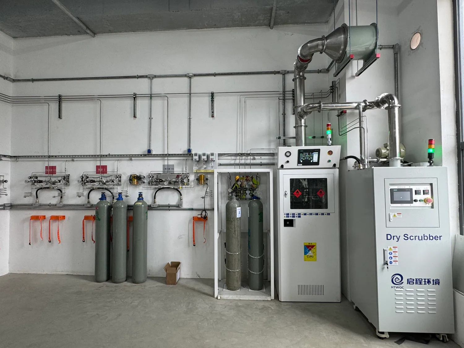
Map residual gas from the source panel through purge, collection, treatment and final discharge—with clear ownership of every interface.
THE DESIGN QUESTION
Plan the whole path, not just the equipment list
A gas delivery design is incomplete if it ends at the instrument inlet. Cylinder changes, maintenance, cabinet ventilation and process equipment can each create a gas stream that must be routed, monitored and, when required, treated before discharge. “Purge” and “exhaust” describe different functions: one removes residual gas or air from a defined line; the other carries a stream to an approved destination. They may meet, but they should not be drawn as one anonymous pipe.
This page helps laboratory and facilities teams define the boundary between gas supply equipment, building exhaust and any abatement package. It covers planning questions for specialty-gas projects, not a universal treatment recipe. The waste-gas composition, concentration, flow, reaction products, local emission rules and permit conditions determine the final method. Qualified process, environmental and safety specialists must approve the result.
01 / STREAM REGISTER
Inventory every gas stream and its origin
Start a stream register alongside the gas-use schedule. Identify the gas cabinet or enclosure exhaust, cylinder-change purge, process-tool exhaust, relief or vent line, vacuum-pump discharge and any routine sampling flow. For each stream, record the possible gas constituents, normal and upset flow, pressure, temperature, moisture, particles and expected operating frequency. A treatment package cannot be selected responsibly from the name of the cylinder alone.
Distinguish air-diluted enclosure exhaust from a concentrated process or purge stream. Their flow and contaminant loading can be very different, and they may require different materials, monitoring and treatment. Ask whether two streams are chemically compatible before combining them. Mixing incompatible gases in a shared duct or treatment vessel can create a new hazard rather than simplify the installation.
The stream register should also say where the information came from: supplier data, process-tool specifications, an operating procedure or a calculated worst case. Mark unknowns for confirmation. This creates an auditable basis for discussions among the gas equipment supplier, mechanical designer, environmental engineer and facility operator.
02 / PURGE BOUNDARIES
Define the purpose of each purge connection
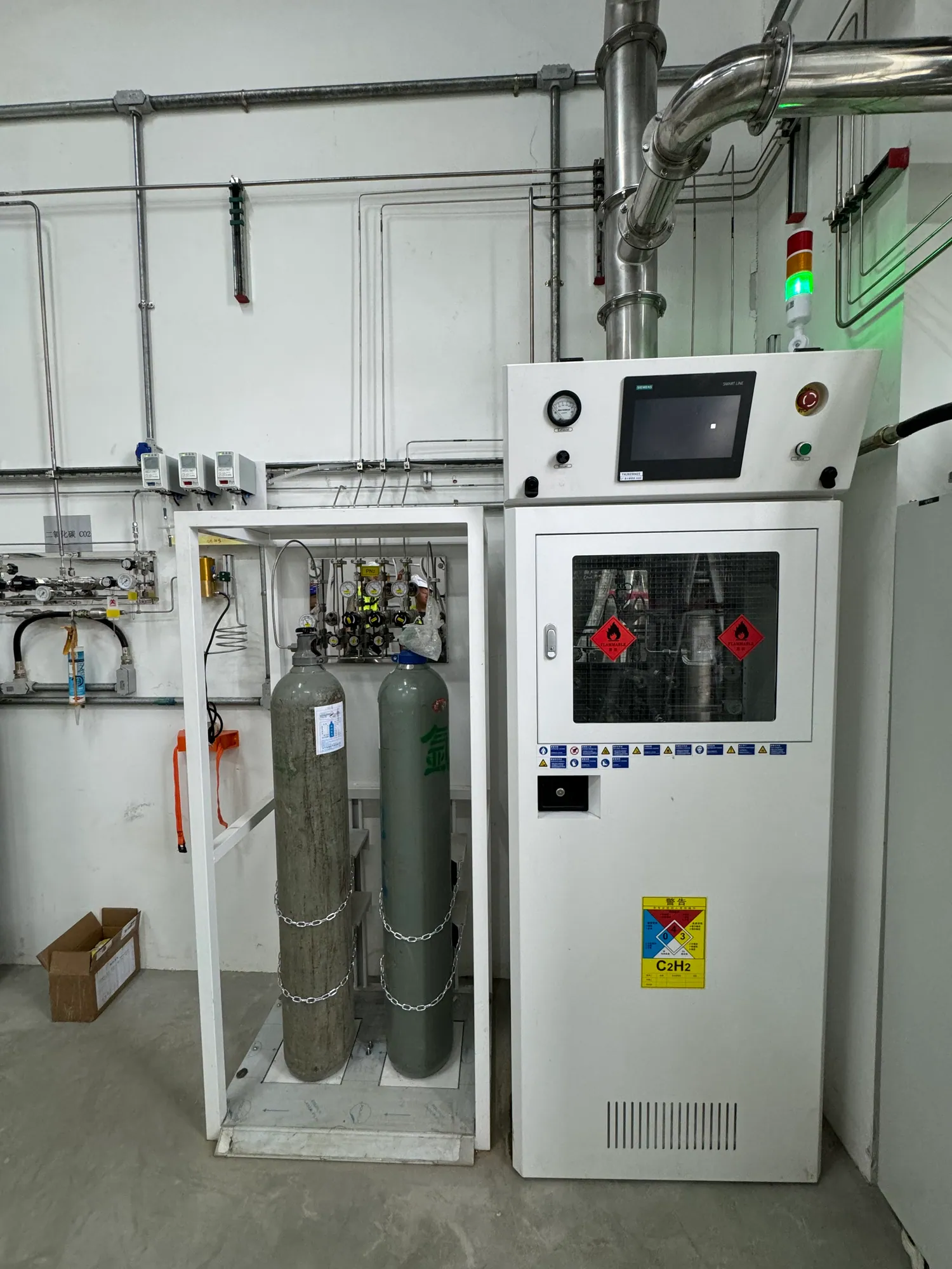
Purging can remove air before a clean or reactive gas is introduced and remove residual process gas before a connection is opened. The approved method depends on the medium and the system geometry. A purge circuit needs a compatible purge gas, controlled valves, a defined vent or treatment destination and a way to verify that the intended boundary has been reached. Do not assume that a pressure gauge alone proves a line is safe to open.
The design should identify what volume is being purged: a cylinder pigtail, regulator, manifold branch, distribution line or process tool. Dead legs, check valves and isolated pockets can prevent a nominal purge path from reaching every volume. The project team should review the schematic in each operating mode—start-up, cylinder change, maintenance and shutdown—and document the resulting valve and vent states.
For high-purity service, the goal may include removing oxygen or moisture that would contaminate the experiment. For hazardous service, personnel exposure and an approved discharge route are central. One purge procedure may serve both goals only if it has been engineered and verified for both. Our corrosive and high-purity gas guide explains the clean-gas side of this interface.
03 / ABATEMENT CONCEPT
Select treatment from chemistry and load
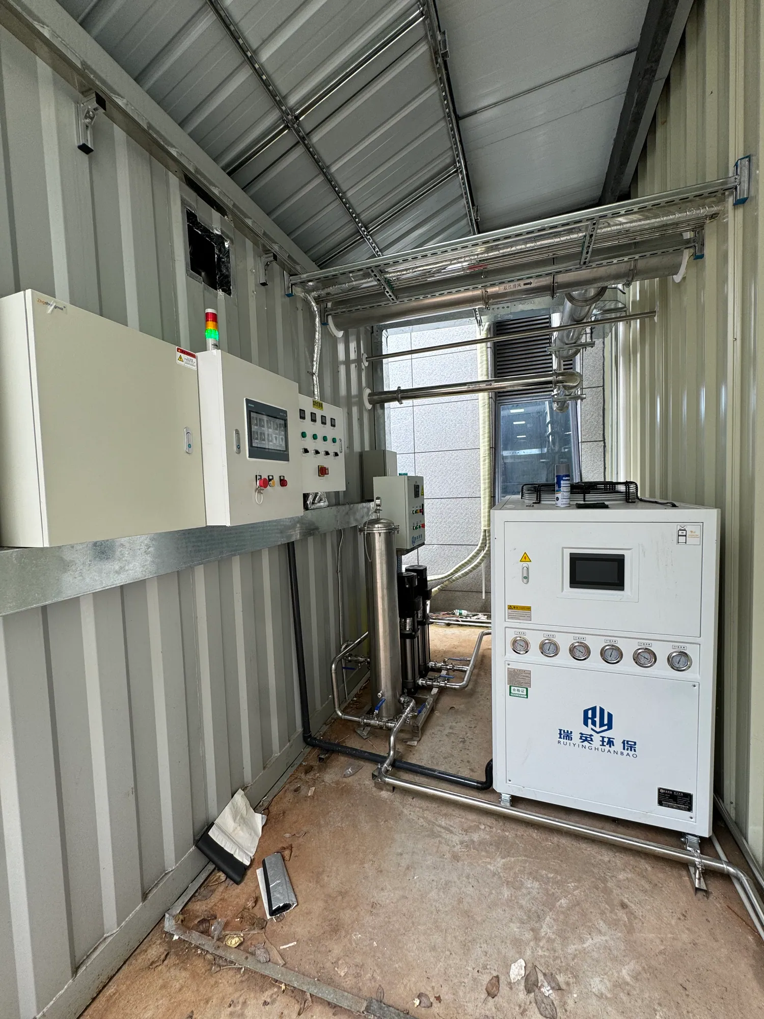
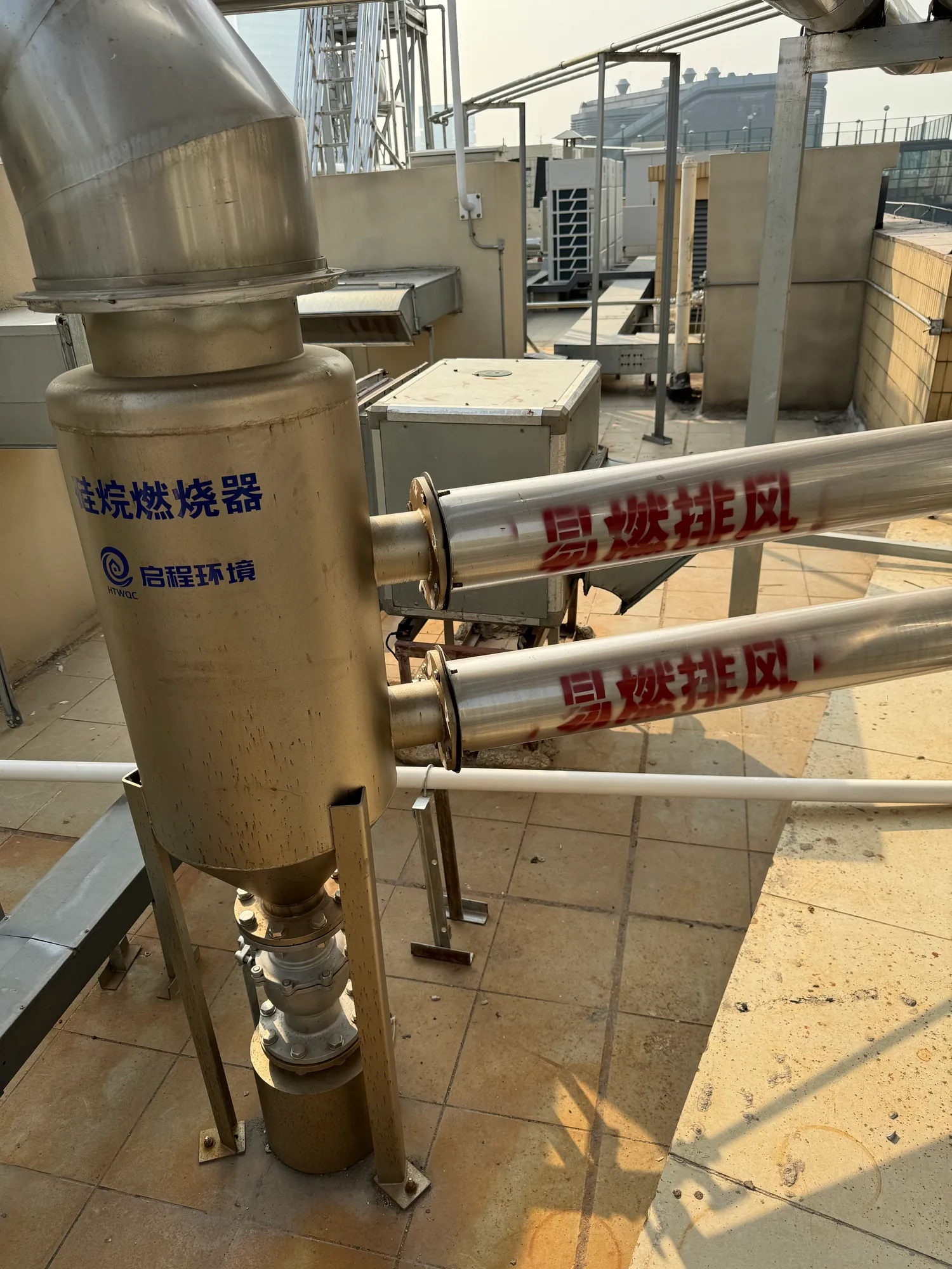
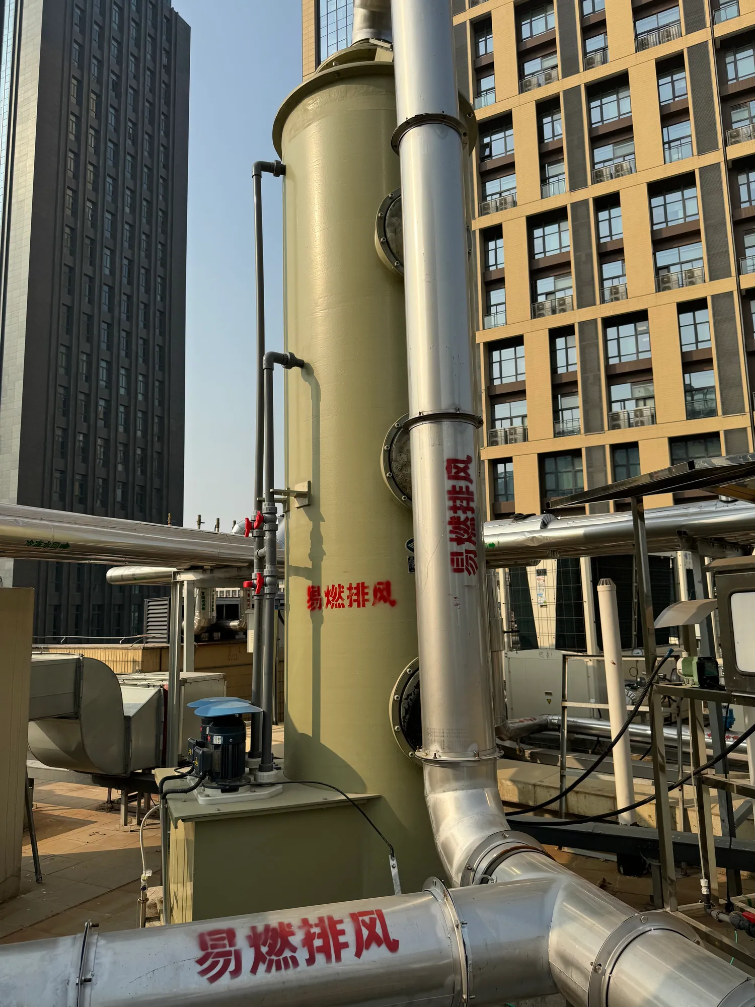
Dry adsorption, wet scrubbing, thermal or catalytic methods and other treatment technologies can be appropriate for different gas streams. Each has limits concerning gas chemistry, loading, byproducts, utilities, monitoring and maintenance. The treatment method should follow a documented stream characterization and environmental review. A photo of an outdoor vessel does not establish its function or suitability for a new project.
Calculate both routine and upset cases. A system that handles a small continuous purge may be overwhelmed by a credible cylinder release or process upset unless that event is isolated through a separate safety strategy. Conversely, sizing every component for an undefined extreme can produce an impractical project. Define the design cases, the expected duration, any upstream automatic isolation and the permitted residual emission.
Consumables and secondary waste matter. A dry medium eventually needs replacement; a wet treatment may create a liquid waste stream; a thermal method may require fuel or power and suitable downstream handling. The operations team needs a realistic plan for sampling, alarms, replacement, waste management and shutdown. The final selection should be made with the treatment specialist and local environmental requirements.
04 / BUILDING INTERFACE
Design the duct and discharge as part of the system
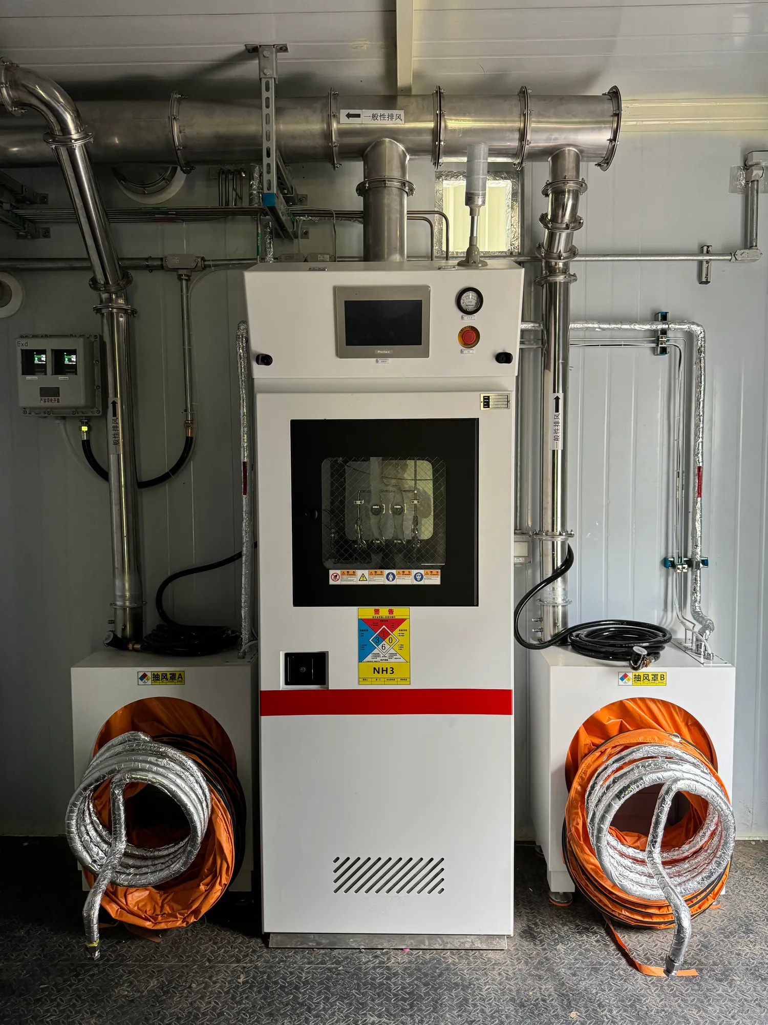
The route from gas cabinet or process tool to treatment equipment must be compatible with the stream, accessible for inspection where required and coordinated with building pressure and exhaust capacity. The mechanical designer should evaluate materials, condensation, corrosion, fan placement, leakage and maintenance access. A gas panel vendor can specify the required connection and flow envelope, but it cannot approve the entire building exhaust path without that coordinated design.
Discharge location is a site issue. The facility must assess recirculation to air intakes, occupied areas and nearby buildings under applicable local requirements. If treatment is required, sampling and monitoring points need to be placed where they can represent the actual outlet condition. The route should also clarify whether normal room exhaust, cabinet exhaust and process exhaust are separated or combined under an approved basis.
A useful interface schedule names each connection size, expected range of flows, pressure condition, material, control signal, alarm and responsible contractor. It also identifies who supplies the fan, duct, damper, treatment unit and electrical control. Without this schedule, a project can have all equipment on site yet no agreed safe path between it.
05 / CONTROL LOGIC
Make fault behavior and monitoring explicit
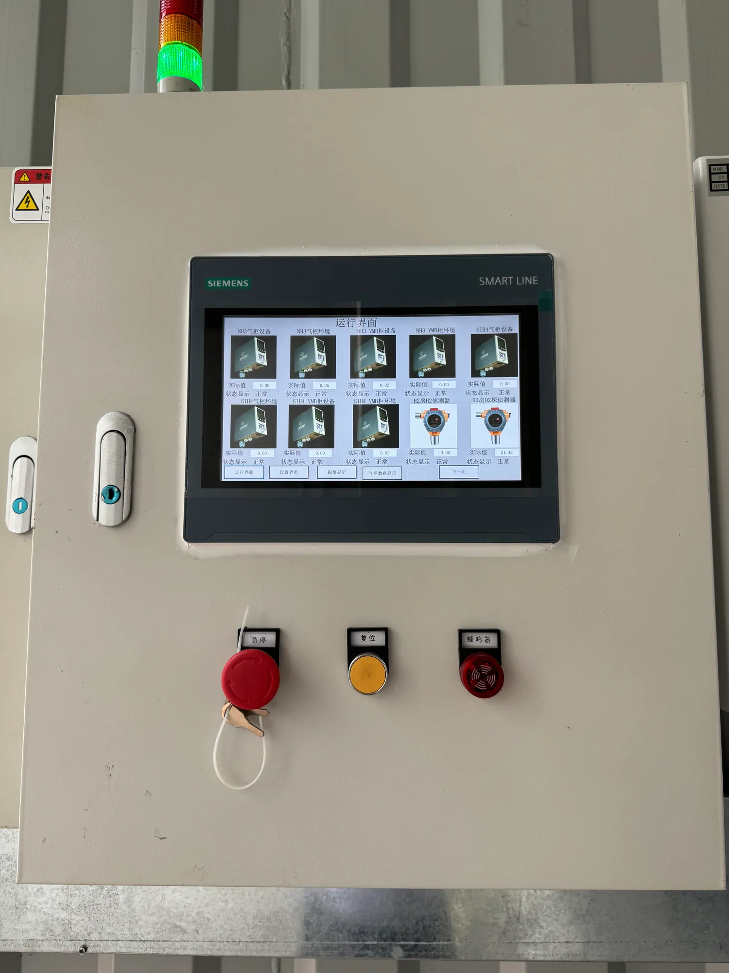
Monitoring may include exhaust flow or pressure, cabinet status, gas detection, treatment-unit condition and downstream emission parameters. Each instrument should answer a specific question and have a named owner for calibration or inspection. A visible display is not proof that the relevant hazardous condition is measured. The control philosophy should distinguish warning, shutdown and maintenance indication.
Build a cause-and-effect matrix with the gas-supply team and the building-control team. For each input, state the alarm, valve position, source isolation, fan or treatment response and reset authority. Review power loss, network loss, low exhaust flow, detector fault and treatment-unit trip as separate events. A fail-safe position depends on the hazard and the process design; it should not be inferred from a generic equipment brochure.
Commission these responses as an integrated system. Simulate permitted fault states, record the actual result and correct mismatches before handover. The facility then needs an alarm-response procedure that tells people what to do, which area to avoid and who may restore gas flow. Interlocks protect only when they remain tested and understood.
06 / VERIFICATION
Handover the downstream boundary with evidence
Acceptance records should connect the stream register to the installed equipment. Verify line identity and destination, materials where specified, integrity tests, airflow or pressure performance, monitoring calibration, treatment operation and control-interface behavior. Emission verification must use the method and limits approved for the project. No generic webpage can certify a particular installation or replace the local permit.
Deliver an as-built process and instrumentation diagram, equipment manuals, control logic, test results, sampling plan, consumable replacement criteria and waste-handling responsibilities. Include instructions for a cylinder change, maintenance purge, abnormal shutdown and return to service, each approved by the facility. The person maintaining the system should be able to follow the gas from its source through the final discharge point.
Revisit the design when a new gas, tool or process recipe changes the waste stream. A new corrosive constituent may alter duct compatibility; increased flow may change fan capacity; a new byproduct may make the chosen treatment ineffective. Change control is part of the solution, because research facilities rarely keep a fixed gas list for the life of the building.
PROJECT DECISIONS
Questions that make the specification stronger
Keep enclosure exhaust separate from concentrated process streams when required
A ventilated gas cabinet can move a large volume of relatively dilute air, while a purge or process vent can carry a smaller but more concentrated stream. Treating these as identical flows can lead to incorrect materials, fan sizing or abatement selection. Map the origin, expected chemistry and flow envelope of each stream before deciding whether they can meet. Compatibility, backflow prevention and treatment capacity are part of that decision.
The location of a release also matters. A cabinet exhaust route protects the room only if the enclosure and airflow work as intended. A process-tool vent may have a different pressure and be subject to an equipment interlock. A relief discharge can represent an uncommon but significant event. A single line on a drawing should never hide these different operating modes.
Write an operating narrative for purge and shutdown
A process and instrumentation diagram identifies valves and instruments; an operating narrative describes what people and controls do. It should cover initial preparation, normal running, source change, planned maintenance, fault shutdown and return to service. For each state, describe which part of the gas path is isolated, where residual gas can travel and what confirms the system is ready for the next state. The narrative is reviewed and approved by the facility’s responsible specialists.
This exercise often reveals missing interfaces. A purge may require a gas supply that was omitted from the utility schedule. A vent may terminate at a treatment package that has no confirmed capacity. A cabinet may shut down gas on low exhaust flow while the process tool continues to request it. Resolving these conflicts on paper is less disruptive than discovering them during commissioning.
Evaluate treatment by performance and maintainability
The selected abatement method must work for the stream’s chemistry and loading, including foreseeable changes in the research program. Ask how performance is demonstrated, where the outlet is sampled, how consumables are monitored and what happens when the unit is unavailable. A treatment unit that meets an initial specification but cannot be safely maintained or monitored is not a complete solution.
Secondary waste and utilities are part of the decision. If media or liquid must be replaced, identify who handles it and under which site procedure. If power, water, compressed air or heat is required, include those loads in the facility design. State whether a treatment trip isolates the upstream gas or merely raises an alarm; the correct behavior follows the hazard assessment.
Commission the whole route from source to discharge
A useful integrated test begins with the source and traces the intended path through purge connection, enclosure or tool vent, duct, treatment equipment and final outlet. Confirm line identification, direction, expected flow or pressure, status indications and the specified alarm responses. Where an environmental limit applies, the verification method must match the permit and approved design. Component factory testing cannot establish the behavior of the assembled facility.
Include the responsible people in acceptance. Gas equipment, mechanical, controls, environmental and laboratory operations teams should see the same final schematic and test record. This prevents a handover in which each contractor has verified its own package while no one has verified the boundary between packages.
Use a stream register to manage future experiments
Research changes can alter the exhaust composition faster than the building infrastructure changes. Keep the stream register with the laboratory change-control file and update it when a new gas, cylinder concentration, tool recipe or operating duration is proposed. Recheck whether the duct material, treatment method, monitoring and permit still cover the revised stream. A spare connection does not prove downstream capacity.
For procurement, share the register, source schematics, available exhaust drawings and desired performance criteria with bidders. Request an interface schedule and a list of assumptions. LGF Lab Gas Flow can support the gas delivery and purge-side definition, while the qualified exhaust and treatment specialists establish the building and emission design. The boundary should be written down in the offer and in the final handover package.
Example: a cylinder-change purge and a process-tool vent
A source-panel purge may operate briefly during cylinder change and carry residual specialty gas from a small internal volume. A process tool may vent throughout an experiment and generate reaction byproducts not present in the cylinder. Their duty cycles and compositions can differ even when they originate from the same gas supply. Put both in the stream register, and do not assume one treatment method or duct material will serve them without analysis.
The interface drawing should identify each origin, isolation device, expected flow range and downstream destination. This lets the treatment specialist assess whether separate handling, compatible combination or a specific sequence is appropriate. It also helps operators recognize which stream remains active during maintenance.
Example: the treatment unit is unavailable
A treatment package can be offline because of a fault, planned media change or lost utility. The project must decide what happens upstream: does gas supply isolate, can a safe process stop in stages, and which alarms reach the lab and facilities team? The answer depends on the gas hazard and process, so it belongs in the approved cause-and-effect matrix rather than an assumed default.
The handover test should demonstrate the specified behavior and document the reset authority. A laboratory that understands normal operation but not this fault condition has an incomplete operating plan. It should also know whether the treatment unit requires a standby arrangement or whether a controlled interruption is acceptable.
Related systems and the enquiry boundary
LGF Lab Gas Flow can help define source cabinets, purge-side valves and regulators, and monitoring interfaces. The exhaust duct, abatement technology and emissions approval require coordination with qualified mechanical, environmental and safety teams. A clear scope shows how these packages connect rather than presenting a single product as the whole answer.
When contacting us, share the gas list, purge schematic, process-tool vent information, existing duct drawings and any emission or permit criteria. If these are incomplete, we can identify the missing boundary data before a detailed equipment proposal is prepared.
START A TECHNICAL DISCUSSION
The inputs required for an exhaust and purge review
Useful quotations begin with a clear operating envelope and a visible division of responsibility. Send the available information; unresolved items can be identified during review.
- Gas and process-stream composition, SDS information and normal/upset flow cases.
- Source panel, cabinet, tool, purge and relief schematics with each vent origin identified.
- Existing exhaust capacity, routing, discharge location, environmental permits and monitoring points.
- Proposed control signals, alarm recipients, isolation devices and power-loss behavior.
- Treatment performance criteria, secondary-waste handling and operations responsibilities.
FREQUENT QUESTIONS
Questions teams ask before selecting equipment
Is cabinet ventilation the same as gas treatment?
No. Ventilation carries a gas stream away from an enclosure; treatment changes or captures constituents when the project requires it. Both functions must have an approved destination.
Can all purge streams share one exhaust line?
Only after chemical compatibility, flow, backflow, pressure and treatment capacity have been reviewed. An unreviewed common line can create a new hazard.
How do we select a scrubber or other treatment unit?
Characterize the stream and operating cases, then have a qualified treatment and environmental specialist evaluate methods, performance, byproducts and local requirements.
What should be tested at handover?
The agreed line integrity, exhaust performance, sensors, treatment operation, alarm and shutdown logic, and any permit-specific outlet condition.
TALK TO LGF Lab Gas Flow
Turn the gas list into a reviewable system scope.
Share the room plan, gases, instrument requirements and available building interfaces. We can help define the source, control and distribution equipment for your project.