
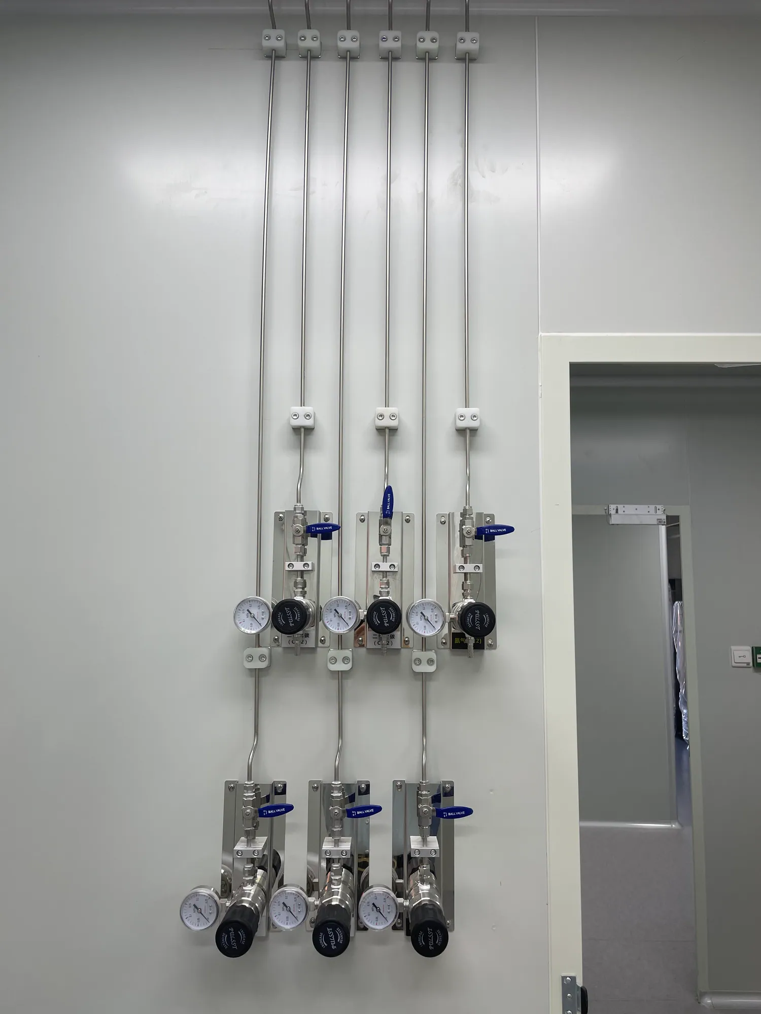
RESEARCH LAB PLANNING / SOLUTION 03
Compact Gas Supply for Small Research Laboratories
Right-size the source, distribution and point-of-use layout for a small research team without losing the ability to inspect, maintain and expand it.
THE DESIGN QUESTION
Plan the whole path, not just the equipment list
A small research laboratory may need only two or three gases today, yet its equipment changes quickly. A compact gas supply system therefore needs a short, understandable path from source to instrument, a layout that people can maintain, and reserved capacity based on a realistic research plan. Oversizing every part wastes space and money; installing a temporary collection of unmarked hoses can make future experiments hard to support.
This guide is for principal investigators, laboratory managers and facilities teams fitting out a new room or upgrading an existing research bench. It focuses on the choices that distinguish a small laboratory from a building-wide centralized laboratory gas supply system. Hazardous gases still require their own gas-specific safety review: a small room does not make hydrogen, toxic or corrosive service low risk.
01 / ESTABLISH DEMAND
Count instruments and operating cases before drawing lines
Create a point-of-use schedule for every instrument. Record the gas, connection, required inlet pressure, normal flow, peak flow, run duration and whether several devices run at once. Ask researchers which instruments are confirmed, which are likely within the next few years and which are only speculative. The answer separates real spare capacity from expensive empty infrastructure.
A research laboratory gas supply may serve chromatography, sample preparation, glovebox support, materials testing or a few benchtop devices. Their duty cycles differ. One shared nitrogen source may be sensible when several instruments draw a compatible grade and can tolerate the same supply arrangement. Separate lines may be required when purity, pressure, gas identity or contamination risk differs. Do not combine services because they happen to use the same wall.
Build a simple room diagram that marks source access, benches, doors, ceiling service space, exhaust connection and possible future equipment. Walk the route with the people who will change cylinders and service instruments. The shortest line on a drawing is not always the safest or easiest line to maintain.
02 / SOURCE STRATEGY
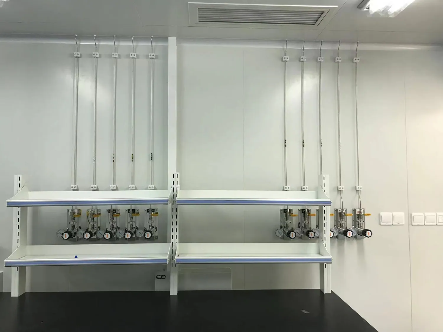
Choose between local cylinders and a shared source
A local cylinder can be practical for intermittent, low-volume, nonhazardous use where the room and facility approve it. A shared cylinder location or small manifold can make sense when several instruments need the same gas or when cylinder changes near active benches are disruptive. Gas generation may be another option for selected routine demands, but it has its own utility, maintenance and quality requirements. Compare complete operating arrangements rather than the purchase price of a regulator alone.
Evaluate cylinder delivery route, floor space, restraint, access to valves, replacement frequency, source pressure and whether a reserve supply is necessary. A laboratory gas manifold system should be justified by continuity and workload, not installed automatically because a larger facility uses one. A small two-bank arrangement may be enough for a critical instrument; a single cylinder may be adequate for occasional tests if interruption is acceptable.
If any gas is flammable, oxidizing, toxic or corrosive, the source decision belongs to the facility safety review. A compact layout must still accommodate required containment, ventilation, detection and emergency controls. Our flammable gas supply guide addresses one of those higher-risk cases.
03 / POINT OF USE
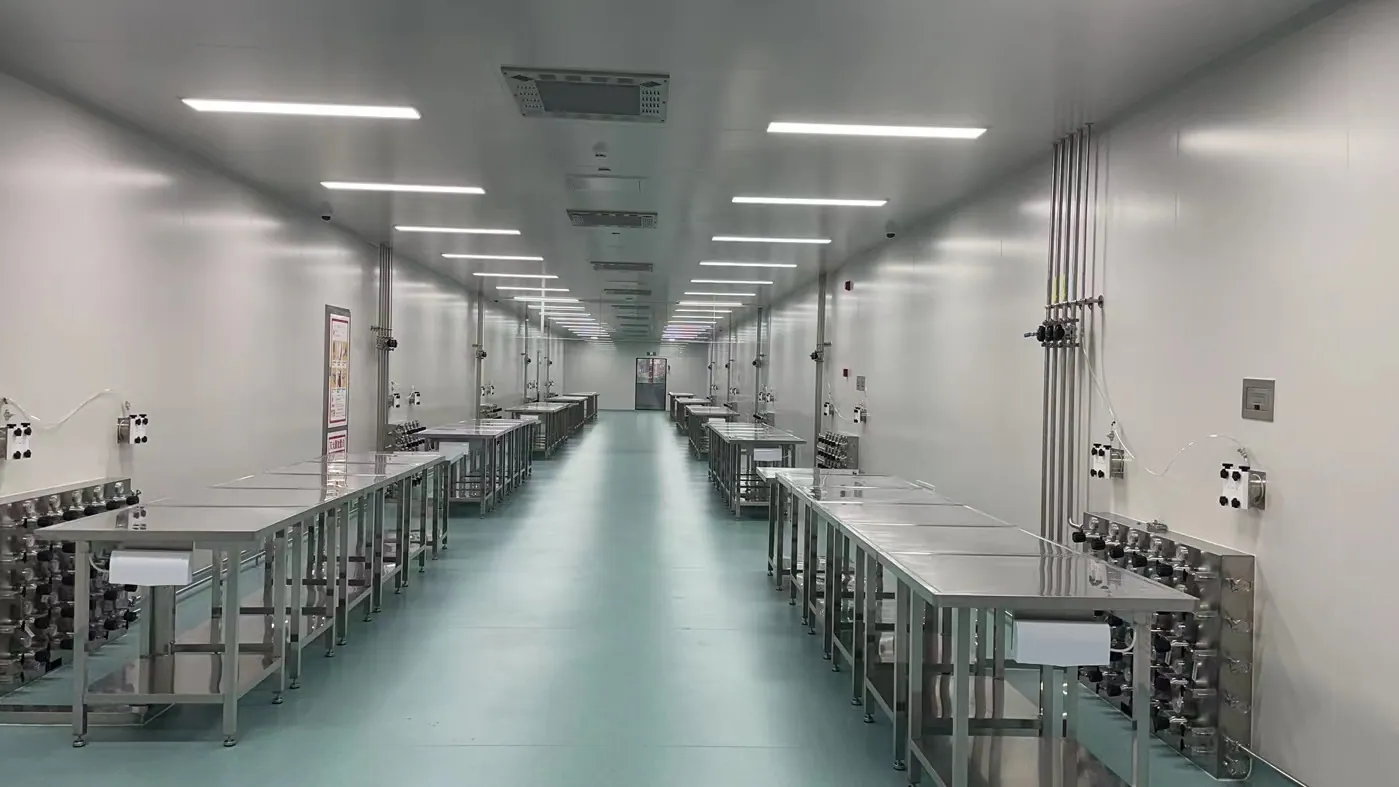
Put pressure control where users can understand it
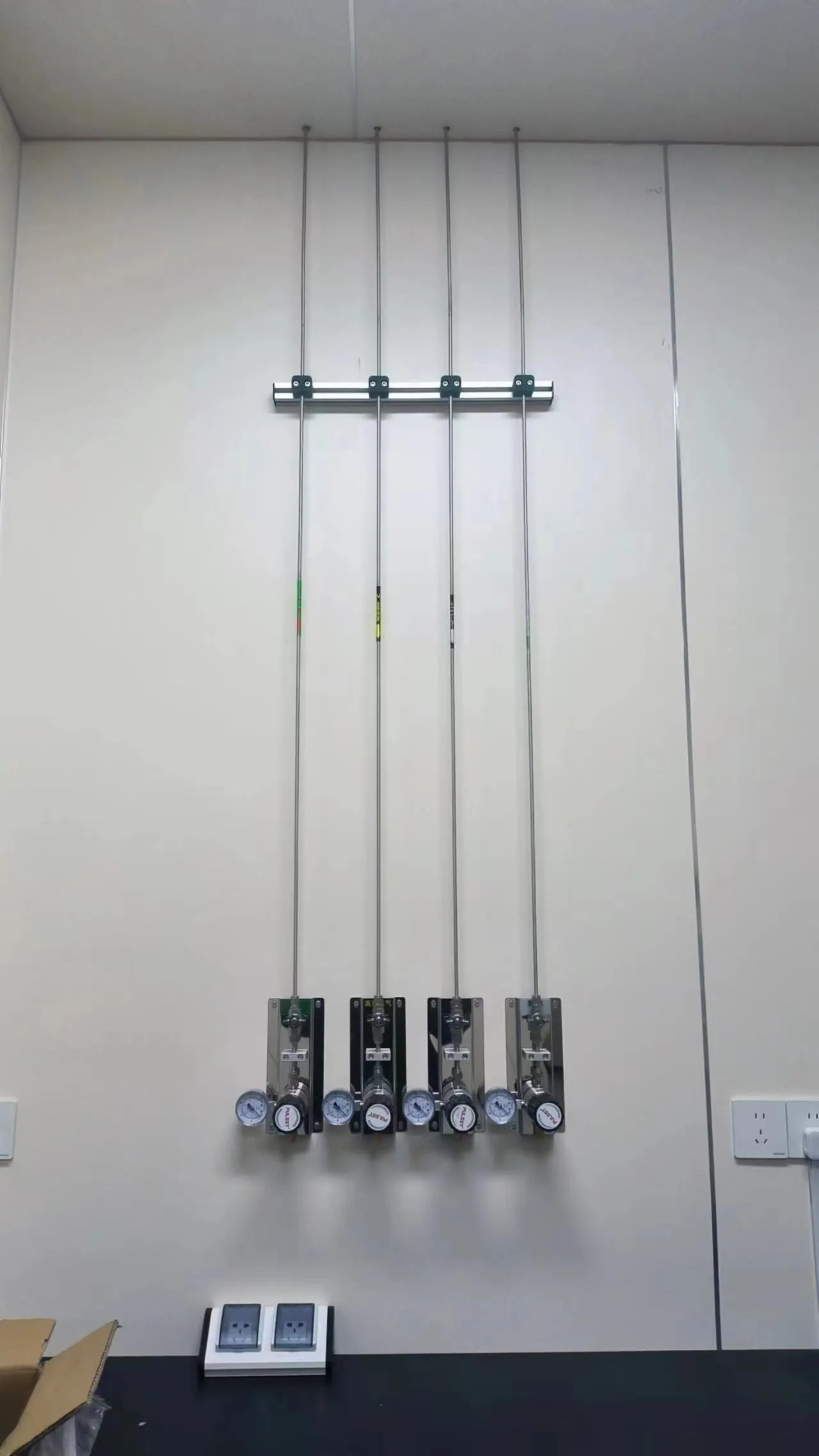
A local panel or terminal can give researchers a clearly labeled outlet and shutoff near each instrument. The panel should show the gas identity, the branch served and the pressure-control function. Avoid clustering all outlets in a corner if users would need long flexible connections across benches. At the same time, avoid one complex panel for every small instrument when a simple shared arrangement will meet the demand.
Pressure regulation may occur at the source, near the use point or in stages. The right arrangement follows the cylinder pressure, line length, pressure drop, instrument tolerance and number of users. If a shared upstream regulator feeds multiple instruments, a change in one branch can affect the others. Local pressure control can help isolate user adjustments, but only when it is selected for the necessary flow and inlet conditions.
Specify final connections early. An instrument supplier may require a particular inlet fitting, hose material or pressure stability. A point-of-use laboratory gas system is most useful when the outlet, instrument connection and bench location are coordinated before furniture and equipment are fixed. The result should be a straightforward user experience: identify the correct gas, confirm pressure, isolate the point and know whom to call if the condition is abnormal.
04 / DISTRIBUTION
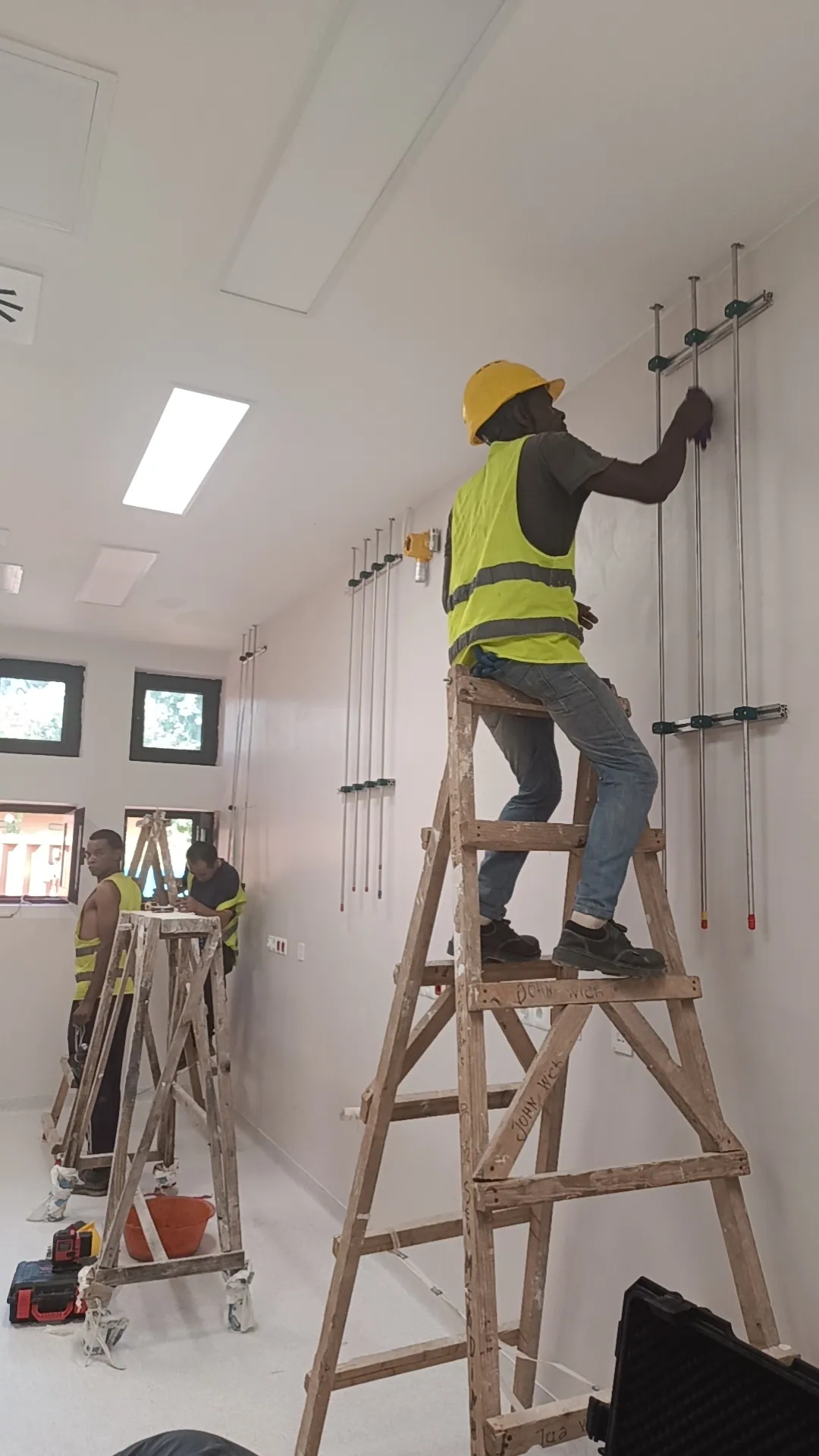
Route a small system for visibility and future change
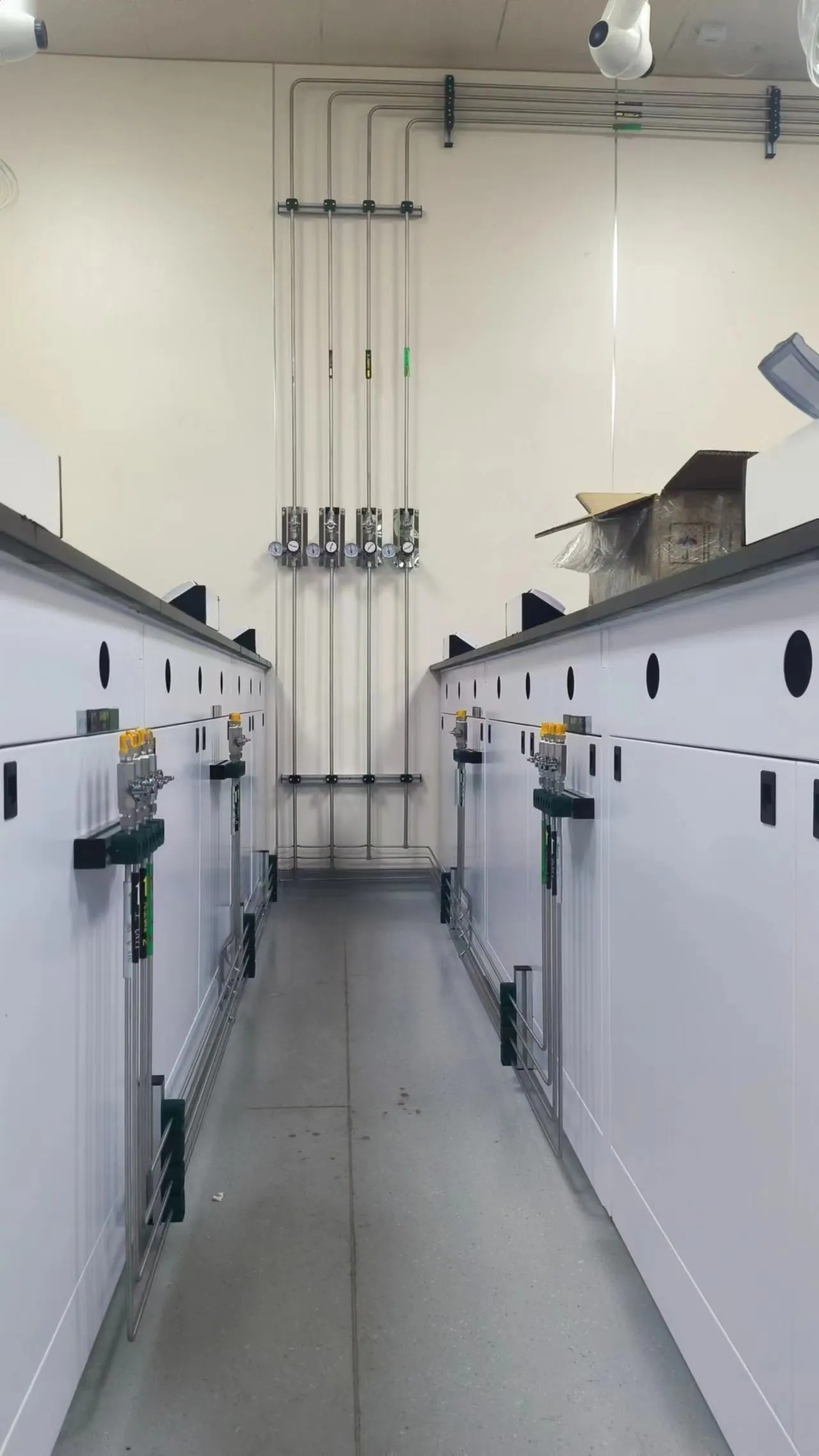
Small laboratories often face limited ceiling voids, crowded service walls and changing bench positions. A tidy distribution route should protect the line, make labels visible and allow inspection of accessible joints. Decide where the line crosses a room, where branches split and which points can be isolated without shutting down every instrument. The routing drawing should also show abandoned or capped outlets, because undocumented spare branches are a frequent source of confusion later.
Material selection still follows gas compatibility and purity. Ordinary utility-grade delivery and an ultra-high-purity analytical line may require different tubing, components and installation practices. Do not impose a cleanroom specification on every benign service, and do not assume a basic line is acceptable for a sensitive instrument. The project should map each service to its own design basis.
Reserve expansion space deliberately. A blank wall or a labeled capped branch is only useful when its capacity, isolation and future connection method have been thought through. It is often better to install a small, well-documented system with a defined addition point than a large manifold with multiple unused outlets whose condition will be difficult to verify years later.
05 / PHASED DELIVERY
Set a realistic scope and cost boundary
A meaningful budget comparison includes source equipment, tubing, valves, point-of-use panels, supports, labor, testing, building interfaces and documentation. The cheapest component list can become expensive if it overlooks exhaust, electrical controls or access work. Conversely, a large automatic changeover system can be excessive for one occasional instrument. Ask suppliers to show a base scope and clearly separated options for continuity, monitoring and future branches.
Phasing can protect the research budget. Phase one may serve confirmed instruments and install the safe route and isolation provisions for likely growth. A later phase can add a new gas or branch after the experiment is approved. This requires an as-built schematic, spare-capacity calculation and change-control process. Without those records, “future-proofing” becomes a vague promise rather than a usable design feature.
For a custom laboratory gas pipeline system, give bidders the same demand schedule and room drawing. Ask them to identify assumptions about cylinder location, pressure, flow, line length and commissioning. A comparable scope makes the quotation useful for a B2B procurement decision and reduces surprises during fit-out.
06 / OPERATIONS
Handover should be simple enough to use
A small team often does not have a dedicated gas technician on site. The handover package should therefore make normal operation clear: which source feeds which outlet, how a cylinder or generation unit is changed by authorized personnel, what pressure is expected, who owns alarms and when maintenance is due. The installed labels and schematic should use the same gas names and point numbers.
Commissioning verifies the installed route, not just the equipment shipment. Include appropriate pressure and leak tests, functional checks of each outlet, and confirmation that any required ventilation or alarm interface acts as designed. If a line serves analytical work, include the agreed cleanliness or purity verification. Test limits and methods are set by the service, not by a generic small-lab checklist.
After handover, review the schedule when new instruments arrive. A device with a higher peak flow or a different gas grade can invalidate the original source selection. A compact system stays useful because it is understandable and changeable under control, not because it anticipates every possible experiment.
PROJECT DECISIONS
Questions that make the specification stronger
The smallest sensible system is not always the shortest one
A cylinder beside an instrument can minimize tubing, but it may place high-pressure equipment in a crowded work area and increase the number of cylinder changes inside the lab. A remote source may create a longer line but free bench space and simplify shared supply. Compare these layouts against the full routine: receiving a cylinder, securing it, connecting it, checking the line, running the instrument, changing the cylinder and responding to an abnormal condition.
The best choice also depends on building constraints. An existing approved cylinder room may make a short central run attractive. In another building, an isolated local supply may be more practical for one intermittent inert-gas user. The project team should record why it selected the source, because future users may otherwise assume the location was arbitrary and move equipment without reassessing the gas path.
Use a simple matrix for phased expansion
List confirmed equipment in one column and likely additions in another. For each gas, state current peak flow, plausible added flow, pressure range and grade. Then identify what can be installed now—such as an adequately sized route or an accessible isolation point—and what should wait until the later instrument is approved. This turns “modular laboratory gas delivery system” from a marketing phrase into a documented design decision.
Spare capacity is not a promise that any future gas will be compatible. A new corrosive or flammable service may need separate materials, containment and approvals even if a capped tube is nearby. Similarly, a larger flow may make the original regulator unsuitable. The matrix should therefore distinguish capacity for the same service from the ability to add a completely different service.
Give researchers an intuitive point-of-use layout
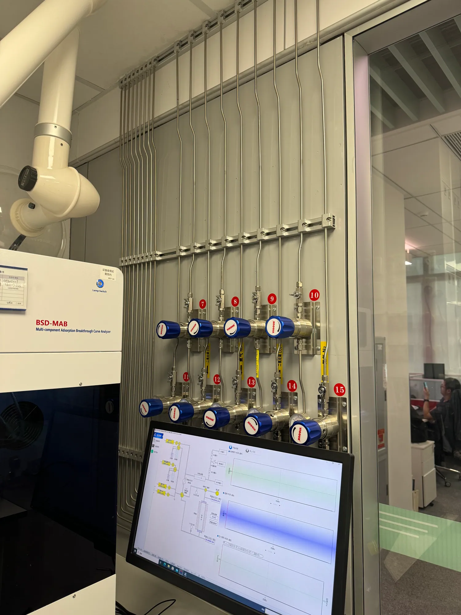
The visible user interface should reduce mistakes. Put the outlet near the instrument it serves, use consistent gas names and branch numbers, and keep pressure gauges readable. If a shared panel serves several benches, label each downstream destination and show the shutoff that isolates it. A user should not have to trace unmarked flexible hoses to learn which cylinder supplies a device.
Think about maintenance access before furniture is installed. A regulator hidden behind a fixed cabinet will be difficult to inspect; a terminal above a bench may be reachable but interfere with tall equipment. Mock up panel height and instrument location on the room plan. This small coordination step often avoids rework that costs more than the panel itself.
Make quotations comparable on total scope
When comparing bids, ask each supplier to show whether the price includes design drawings, source assembly, wall panels, tubing, supports, labels, testing, installation labor, commissioning and training. Also list building works, ventilation, power, alarm integration and permits as included, excluded or by others. A low equipment number with several unstated interfaces is not a reliable project cost.
Compare service life as well as purchase price. How often will cylinders be changed? Can one branch be serviced while another instrument runs? Are common replacement parts available? Is the proposed control sophisticated enough to solve a real need, or will it require maintenance the small laboratory cannot provide? A lean design should be easy to operate, not merely inexpensive to buy.
Protect the system when a research program changes
An instrument move, new gas supplier or revised experiment should trigger a quick review of source capacity, outlet pressure, material compatibility and safety controls. Keep the as-built diagram and point schedule where facilities staff can find them. Photograph the installed labels and update the drawing when branches change. A forgotten capped outlet should never become an informal spare connection.
Plan a periodic walk-through with users. Confirm that labels still match equipment, cylinders remain secured, isolation points are accessible and any alarm or ventilation interface is maintained. These simple observations do not replace formal inspections, but they reveal when a compact layout has gradually become crowded or undocumented. The long-term value of a small system is its clarity.
Example: an analytical bench with three gases
Imagine a small room with one chromatography system and two related instruments. The team needs nitrogen, helium and a process gas, but not every device runs simultaneously. A useful planning exercise lists each inlet, peak draw and quality grade, then shows which sources can serve more than one device. The engineer can compare a compact shared source with separate local cylinders and identify the changeout and routing consequences of each.
The room plan should show accessible source valves and point-of-use controls near the instruments, not a single panel installed wherever wall space remains. If the process gas is hazardous, its containment and detection are reviewed separately. This example demonstrates that “small” describes the project scale, not the engineering rigor needed for each gas.
Example: a research group that expects to grow
A newly funded group may know its first two instruments but only have provisional plans for future equipment. It can commission the confirmed services now and reserve a documented route, panel space or isolation point for a likely same-gas addition. The future flow allowance should be calculated and recorded. If the later instrument uses a different purity grade or hazardous gas, the team revisits the design rather than connecting it to a convenient spare.
This phased approach makes the spending visible. The initial budget buys functioning, tested gas delivery; the reserved capacity is a separately priced option with a defined purpose. Future work then has an as-built drawing and test history from which to proceed.
Related equipment and a practical request for quotation
A compact system may use point-of-use panels, a small manifold or changeover unit, appropriate regulators and labeled piping components. The correct combination follows the room and demand schedule. It should be easy for users to understand and for facilities staff to maintain.
For a quotation, provide a marked room plan, the instrument schedule and any existing utility drawings. Tell LGF Lab Gas Flow which items must be live at opening and which are future options. We can then help define a compact equipment and distribution scope that the facility can evaluate alongside building work and safety requirements.
START A TECHNICAL DISCUSSION
Small-lab information to share before design
Useful quotations begin with a clear operating envelope and a visible division of responsibility. Send the available information; unresolved items can be identified during review.
- A room plan with bench locations, ceiling/service space, doors and cylinder access.
- Confirmed and likely instruments, gas grades, pressure, flow and simultaneous-use cases.
- Existing utilities, approved gas storage, ventilation, power and exhaust provisions.
- Continuity needs, planned growth horizon and budget split between base scope and options.
- Facility safety contacts and the required handover or training documentation.
FREQUENT QUESTIONS
Questions teams ask before selecting equipment
Is centralized supply always better for a small lab?
No. The best arrangement depends on gas hazard, number of instruments, consumption, changeout frequency and available approved source space.
How many spare outlets should we install?
Install only those supported by a credible future plan and a documented capacity and isolation strategy. Unused connections should be clearly identified and protected.
Can several instruments share one regulator?
Sometimes, if pressure, flow, purity and simultaneous demand are compatible. The effect of one user or device on the others must be checked.
What makes a compact system easy to maintain?
Accessible isolation, readable labels, a current schematic, known test points and an operating procedure suited to the facility staff.
TALK TO LGF Lab Gas Flow
Turn the gas list into a reviewable system scope.
Share the room plan, gases, instrument requirements and available building interfaces. We can help define the source, control and distribution equipment for your project.