
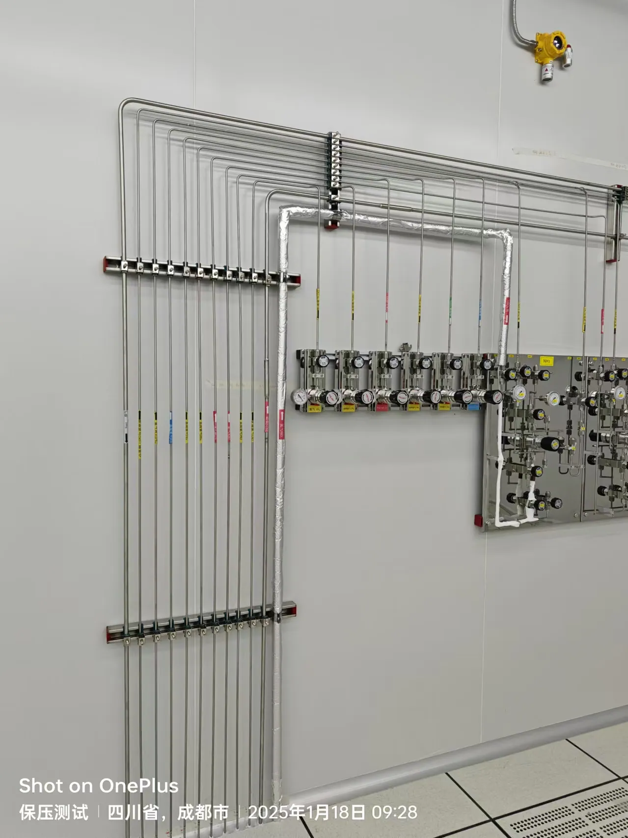
SPECIALTY GAS INTEGRITY / SOLUTION 02
Corrosive & High-Purity Specialty Gas Supply
Design the complete gas path around chemical compatibility, moisture control, containment and measurable purity at the instrument.
THE DESIGN QUESTION
Plan the whole path, not just the equipment list
A corrosive or ultra-high-purity gas line has two simultaneous jobs: deliver the required gas and preserve the condition in which it was purchased. A small amount of moisture, oxygen, particles or incompatible material can change an analytical result, shorten equipment life or create a hazard. Corrosive gases introduce an additional question: what happens to the gas path when the medium encounters air or water during changeout, maintenance or a leak?
This solution is for research, analytical, materials and clean-process teams that need a traceable design from cylinder connection to process tool. It treats purity and containment as properties of the complete path, not as claims attached to one stainless-steel regulator. The final materials, cleaning level, test limits and safety controls are selected for the named gas, mixture, concentration, operating pressure and destination market.
01 / DEFINE THE GAS PATH
Write a gas-by-gas performance specification
Begin with a schedule for each process gas: chemical identity, concentration, carrier gas, supplier connection, certified purity, expected contaminants, pressure, flow, usage pattern and target quality at the instrument. Include the composition of any mixtures. The same distribution route may be unacceptable for two gases that seem similar because their reaction with moisture, elastomers or metals differs. Do not infer a component specification from the cylinder label alone.
Define where purity is measured. A supplier certificate describes the gas at its source; it does not prove purity after a regulator, manifold, long distribution tube and repeated cylinder changes. In a high-purity laboratory gas system, the acceptance criteria may concern moisture, oxygen, particles or process-specific contaminants. The project team should state which parameters matter to the experiment, where samples can be taken, and what test method will be accepted.
Document hazards separately from purity. A corrosive gas can require a ventilated cabinet, monitored enclosure, compatible exhaust connection, local shutoff or special response procedure. A benign high-purity inert gas may need fewer hazardous-gas controls while still demanding strict cleanliness. Keeping these two decision tracks visible avoids overspecifying a safe gas or overlooking the hazard of a clean one.
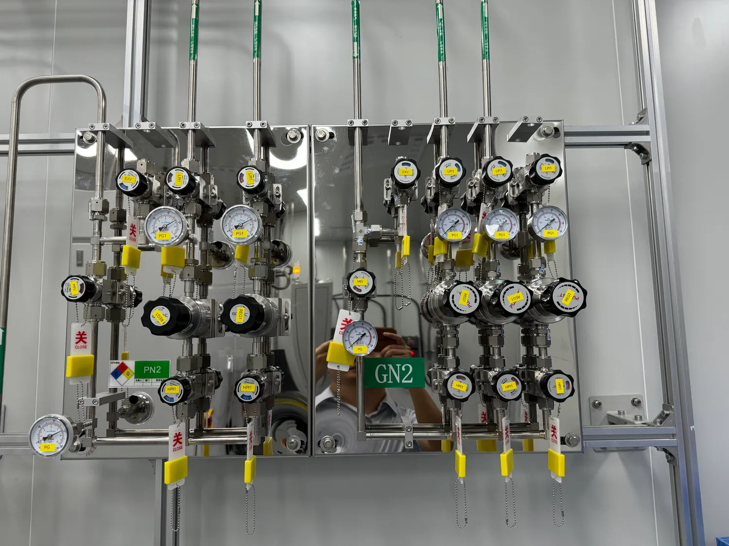
02 / MATERIAL COMPATIBILITY
Select every wetted component for the named chemistry
The materials review covers the cylinder pigtail, regulator body and diaphragm, valves, seals, filters, tubing, fittings, terminal panel and instrument connector. “Stainless steel” is a family of materials, not a complete compatibility statement. Gas composition, moisture content, temperature, pressure and anticipated service life all affect suitability. A 316L stainless-steel laboratory gas line is common in high-purity distribution, yet a project can still require a different alloy, seal or construction for its chemistry.
Ask vendors for the actual wetted-material list and relevant cleaning, surface-finish and leak-integrity information. Verify whether the proposed diaphragm valve, regulator and connection are suitable for the purity target and the corrosive medium. Features that can matter include low internal volume, fewer stagnant pockets and connections that can be assembled repeatably. The most polished component will not compensate for a contaminated pigtail or incompatible seal elsewhere in the path.
Connection design should also consider maintenance. The team needs a way to isolate a module, replace a component and restore cleanliness without exposing an unnecessary length of pipeline to air. This is why the system schematic, bill of materials and maintenance procedure must describe the same boundaries. A generic high-purity gas piping supplier catalogue is a starting point for selection, not a substitute for this compatibility review.
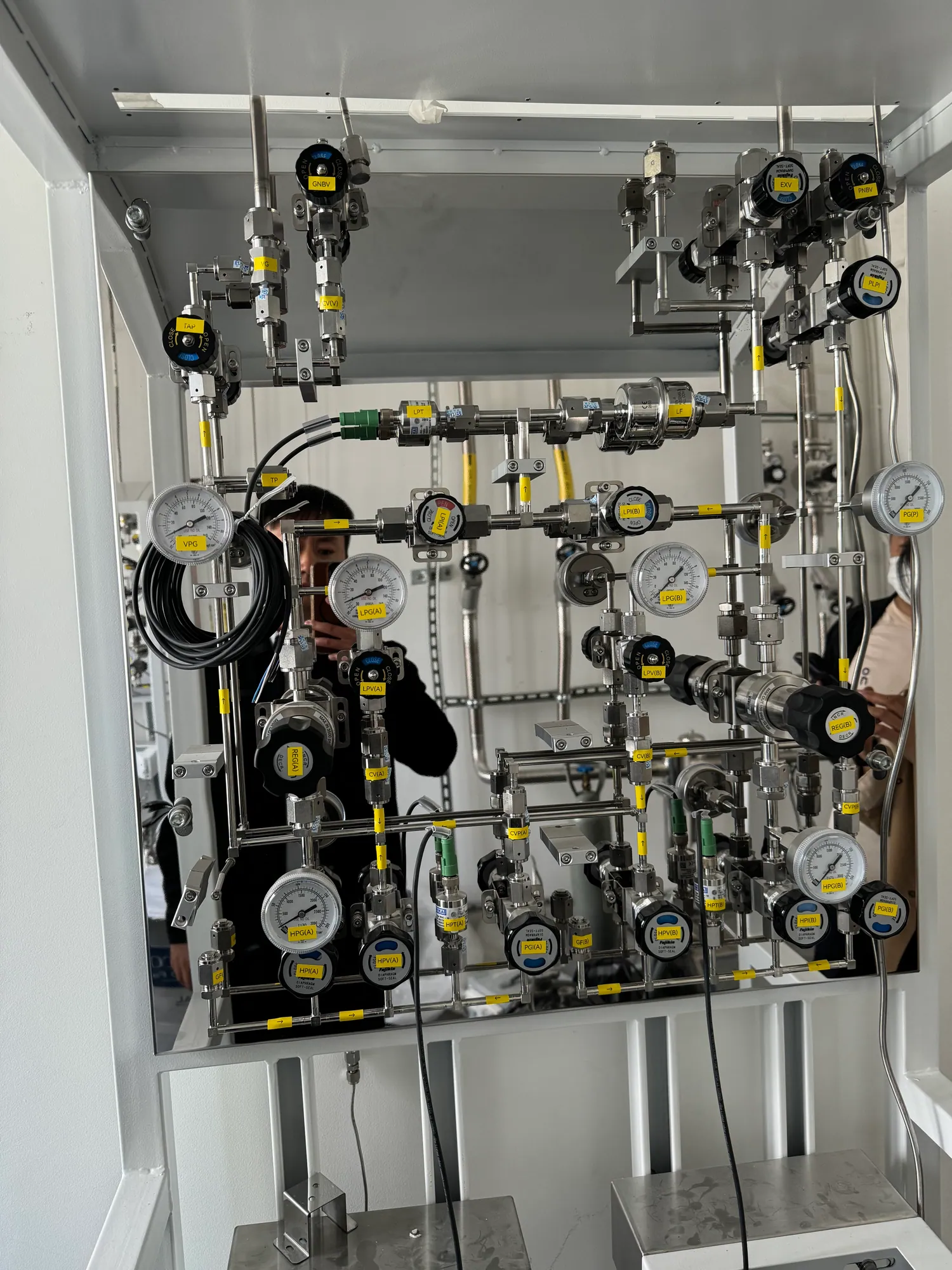
03 / SOURCE & PURGE
Control air ingress at the cylinder interface
Cylinder change is often the point where a clean line meets room air. An appropriate purge assembly and changeout method can limit residual process gas before a connection is opened and remove entrained air before the new source is introduced. The purge medium, source connection, vent destination and sequence must be approved for the specific gas. Some gases react with oxygen or water; a seemingly simple flushing step can therefore become a safety and contamination issue.
The source package may contain an ultra-high-purity lab gas manifold, pressure regulators, isolation valves, check valves, purge connections and monitoring interfaces. Whether it needs one cylinder, two-bank changeover or a cabinet depends on demand and risk. A manifold should not have unnecessary unused branches; each branch adds internal volume and a possible maintenance point. If supply continuity is critical, define how the system transitions between sources without losing the required outlet pressure or cleanliness.
Document the exact boundary between clean gas, purge gas and exhaust. A dedicated purge source may be necessary for some hazardous media; it must not become an unreviewed cross-connection with other services. The downstream treatment or approved exhaust route belongs in the same schematic as the gas panel. Our laboratory gas exhaust and purge guide explores that boundary in more detail.
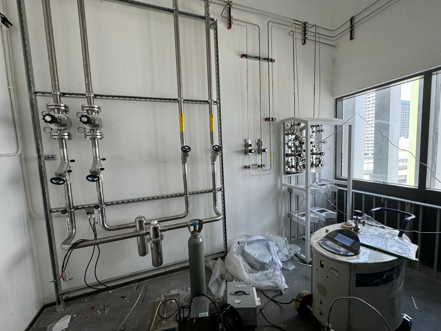
04 / CLEAN DISTRIBUTION
Protect cleanliness through routing and construction
High-purity piping performance depends on fabrication as well as material. Tubing should arrive in the agreed condition, remain protected during storage and installation, and be assembled with practices appropriate to the cleanliness specification. The engineer should decide where welded or mechanical joints are appropriate, how internal surfaces will be protected during fabrication, and how the line will be cleaned, dried and tested before process gas is admitted.
Routing affects both purity and serviceability. Long dead legs can retain air or old gas; unnecessary adapters multiply potential leak points. At the same time, an inaccessible all-welded route can complicate future changes. Design for a realistic research environment: identify the expected expansion points, isolate them, and avoid creating open-ended branches whose state cannot be verified. Label each line and keep an as-built record of its source and destination.
If the laboratory contains both ordinary utility gases and specialty gases, avoid treating every line as one uniform specification. A documented high-purity gas delivery system layout assigns materials, cleanliness and testing requirements by service. This keeps critical paths controlled without spending the entire budget on unnecessary upgrades to unrelated lines.
05 / CONTAINMENT
Integrate the cabinet, monitoring and exhaust interfaces
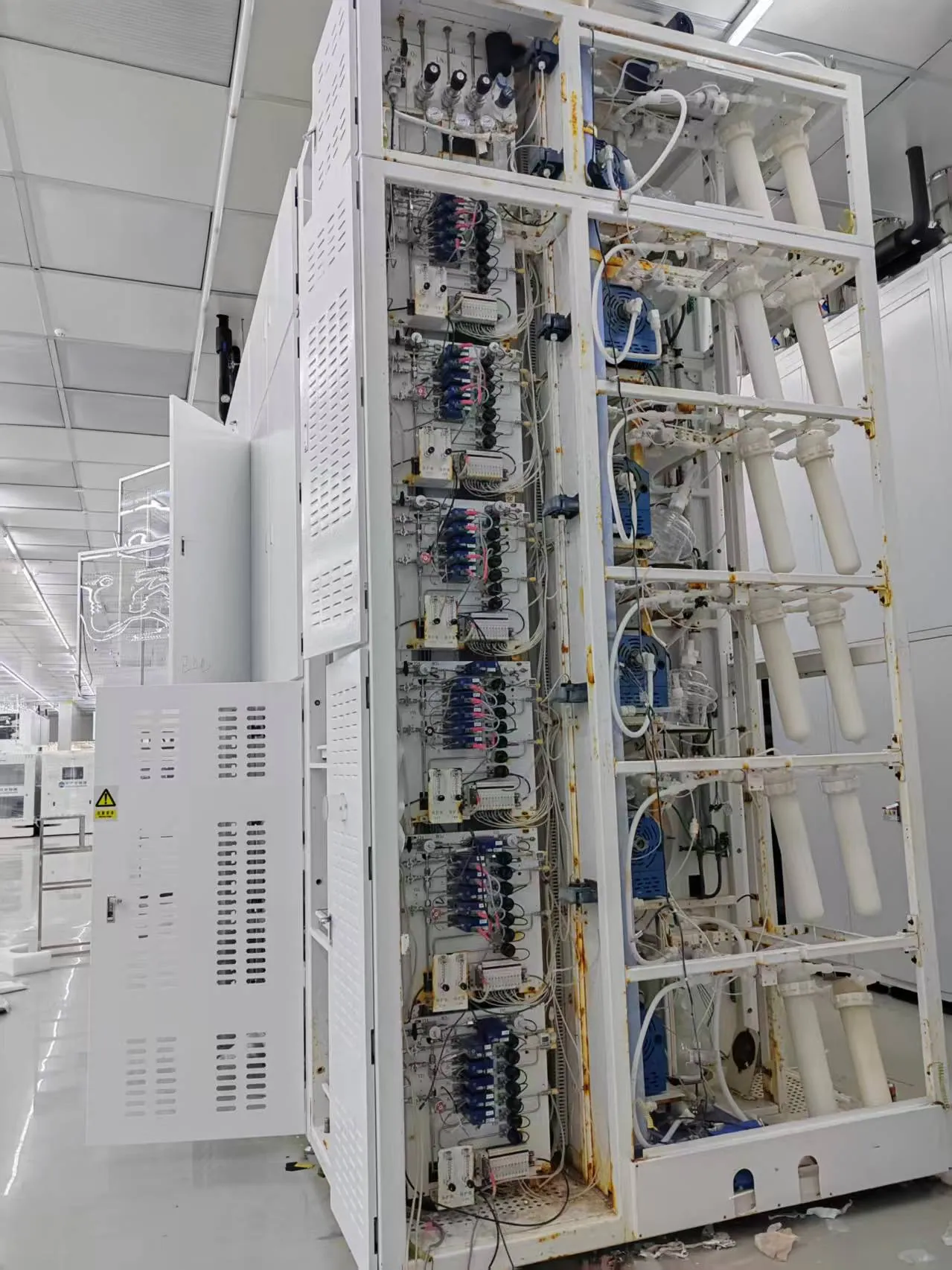
For a hazardous corrosive gas, the cabinet and its exhaust are part of the containment concept. Evaluate the likely release points, enclosure airflow monitoring, gas detection, shutdown valves and the response to power or ventilation failure. The building designer must confirm the duct and discharge arrangement; the gas equipment schedule must show how loss of the required interface affects supply. Do not rely on a cabinet photograph as evidence that any particular gas is approved for that equipment.
Monitoring should match the hazard and the maintenance capability of the facility. Specify where sensors are installed, how their alarms are verified, who receives the signal and how the system is returned to service after a fault. A single detector near a cabinet does not necessarily observe a remote line or point of use. Similarly, pressure indications show operating state but cannot alone demonstrate that a leaking enclosure is contained.
A clear cause-and-effect matrix helps equipment suppliers, facilities and safety staff review the same design. It can identify the initiating condition, alarm, valve state, exhaust response, local indication and reset authority. These interfaces should be tested together during commissioning, because the weakest boundary may sit between two otherwise well-specified packages.
06 / VERIFICATION
Prove the required outcome at handover
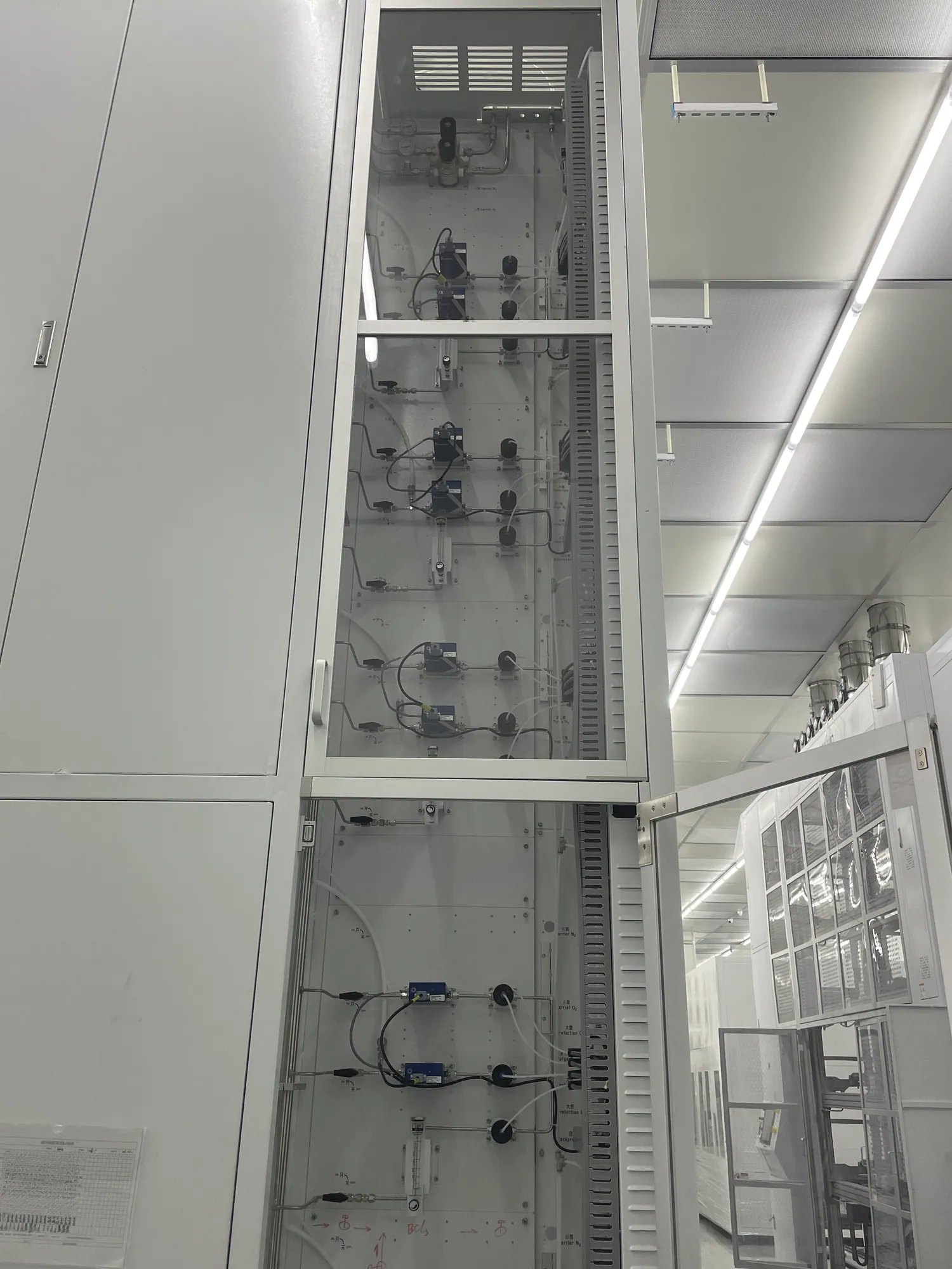
Acceptance should compare the installed system with the agreed performance specification. The project may require material traceability, cleaning records, pressure testing, leak testing, purge verification and contaminant measurements. The methods and pass limits must be set by the process need and applicable requirements; one universal helium leak number or moisture target cannot be promised for all laboratories.
Ask for an as-built schematic, component list, line labels, test records, control logic, maintenance access notes and approved operating procedures. If analytical purity is critical, identify the sample point and test gas before commissioning begins. Repeating a supplier purity claim in the handover pack would leave the actual installed path unverified.
The system should be reviewed when the experiment changes. New mixtures, higher flow, different cylinder suppliers or an added process tool can alter compatibility, capacity and purge requirements. A change-control process keeps the gas path coherent rather than gradually turning a clean specialty-gas line into an undocumented network.
PROJECT DECISIONS
Questions that make the specification stronger
Purity grade is a system target, not a catalogue adjective
A high-purity cylinder can enter a line that contains residual air, moisture or particles. Every added connection, branch and maintenance opening becomes part of the contamination budget. The project should state the impurities that matter to the process and the measurement point at which the target must be demonstrated. A broad phrase such as “UHP quality” cannot replace a numerical, method-specific acceptance requirement when analytical performance depends on it.
The requirement may differ among branches. A research tool sensitive to trace oxygen may need a cleaner route than a utility purge line. A good gas-use schedule identifies these differences before one expensive specification is applied everywhere. It also distinguishes a supplier certificate from installed-system evidence. Both can be useful, but they answer different questions.
Consider contamination during every lifecycle stage
The system can be contaminated before its first operation if tubing is uncapped, tools are dirty or a finished line remains open to humid air. It can be contaminated during normal use by a small leak, unsuitable seal or backflow. It can be contaminated during cylinder change or maintenance when a short section is opened. The design should therefore identify protected storage, clean assembly, leak verification, purge points, isolation and post-maintenance checks as one lifecycle.
This lifecycle view also clarifies procurement. A vendor may provide clean components but not control the installer’s handling. Another may install the line but not supply the gas-analysis method. Define who owns each stage and its record. This is often more valuable than requiring a long list of component features without a corresponding field process.
Containment and cleanliness can pull the design in different directions
A hazardous gas may require more valves, enclosures and monitoring, while a high-purity gas path often benefits from fewer wetted volumes and connections. The answer is not to optimize only one of these objectives. Map the hazard-control boundary and the clean-gas boundary separately, then select components and connection points that satisfy both. A cabinet may contain a source leak, but its internal piping still has to preserve the required gas quality.
Likewise, a very short clean line may be difficult to maintain safely if it lacks isolation and purge connections. The design review should explain each added component’s function: pressure regulation, emergency isolation, sampling, purging or service. If a device has no clear role, it may add cost and contamination risk without improving the system.
Decide how much verification the application justifies
A research laboratory that uses a high-purity inert carrier gas may need different evidence from a sensitive process using a reactive corrosive precursor. Possible records include material certificates, cleaning documentation, pressure and leak tests, particulate checks, moisture or oxygen analysis and control-system functional tests. The project should select the tests that demonstrate its actual outcome and state the acceptance method before construction.
It is also important to define the test boundary. A leak test of a manifold does not cover the final instrument hose. A sample taken at the cylinder cannot validate a remote outlet. Mark test points and isolation valves on the same schematic used for fabrication. If a result fails, that drawing helps the team locate the affected volume and decide whether it needs rework or additional purge.
A quotation should expose unknowns
Send the current gas list, mixtures, SDS files, cylinder connections, process-tool inlet requirements and available room layout. If purity targets are not yet defined, say which experiment is sensitive and what measurement the team can perform. Ask for a proposed component schedule showing wetted materials, pressure ratings, cleaning scope, source arrangement, purge and exhaust interfaces, and acceptance assumptions.
A responsible proposal may list items that remain subject to facility approval, including cabinet ventilation, detector strategy, emission treatment and local codes. This is useful transparency, not incompleteness. It lets the laboratory resolve the external interface before equipment arrives and prevents an attractive component quote from hiding a major building-system dependency.
Example: a clean inert carrier gas versus a reactive precursor
A high-purity helium or argon line for analytical equipment may be driven mainly by moisture, oxygen and particle limits at the instrument. Its source and endpoint need clean connections, a known leakage boundary and a way to confirm the required quality. A reactive precursor can have the same purity challenge plus containment, gas detection, dedicated purge and waste-gas treatment questions. Treating both as “UHP” hides a major difference in hazard controls.
The common discipline is to map the entire path and assign each requirement to an actual component or procedure. A source certificate, regulator specification and tubing grade can support the design, but the assembled path still needs verification. This comparison helps procurement teams ask for a scope that matches the application rather than selecting from a generic purity tier.
Questions that reveal hidden contamination paths
How long can a source connection remain open during changeout? Can air enter through a downstream instrument when the line is depressurized? Are there unused manifold branches or dead legs that are difficult to purge? Which seals, lubricants and cleaning agents contact the gas? The answers may change the design more than a small increase in nominal tubing grade.
Also ask what happens after maintenance. Is a replaced valve clean to the same requirement as the original assembly? Is there an agreed leak and purity verification before process gas resumes? The handover file should specify the return-to-service boundary, not merely the installation test completed months earlier.
How related LGF Lab Gas Flow products fit the scope
Depending on the gas, the source may use a specialty gas cabinet, UHP regulator, diaphragm valves and fittings, and appropriate piping components. A product category is a selection pool, not a guarantee of gas-specific compatibility or achieved purity.
Share the actual process and safety requirements when asking LGF Lab Gas Flow for a quotation. We can align component and panel options to a defined scope while the facility, process owner and qualified specialists approve the chemistry, exhaust and acceptance criteria.
START A TECHNICAL DISCUSSION
Information that makes a specialty-gas quote useful
Useful quotations begin with a clear operating envelope and a visible division of responsibility. Send the available information; unresolved items can be identified during review.
- Gas identities, mixtures, SDS files, cylinder connections and the required quality at each instrument.
- Normal and peak pressure/flow, cylinder-change frequency and supply-continuity need.
- Named wetted-material and cleanliness requirements, or the process limits from which they can be derived.
- Proposed source location, cabinet or enclosure, purge medium, exhaust destination and building interfaces.
- Acceptance test method, documentation expectations and the person responsible for safety approval.
FREQUENT QUESTIONS
Questions teams ask before selecting equipment
Is 316L stainless steel suitable for every corrosive gas?
No. Material and seal compatibility depend on the gas chemistry, concentration, moisture, pressure and temperature. Every wetted component needs a service-specific review.
Does a high-purity cylinder guarantee purity at the instrument?
No. Connections, regulators, tubing, changeout and leaks can introduce contaminants. Define and verify the required condition at the point of use.
Why is purge planning part of the source design?
Cylinder change and maintenance expose connections to air and can leave residual process gas. The approved purge path, medium and exhaust destination must be designed together.
Can an existing line be reused?
Only after its material, history, cleanliness, pressure rating, connection design and testability have been reviewed for the new service.
TALK TO LGF Lab Gas Flow
Turn the gas list into a reviewable system scope.
Share the room plan, gases, instrument requirements and available building interfaces. We can help define the source, control and distribution equipment for your project.