
LABORATORY GAS SAFETY / SOLUTION 01
Flammable Gas Supply System for Laboratories
A coordinated approach to the source, distribution path, detection, ventilation and emergency isolation for hydrogen and other flammable laboratory gases.
THE DESIGN QUESTION
Plan the whole path, not just the equipment list
A flammable gas supply system should be planned as a connected safety system, not a collection of cylinders, regulators and pipes. Hydrogen, methane, acetylene and flammable mixtures are used for chromatography, fuel-cell work, combustion research and materials processing. Their demand patterns differ, but each project needs a defined source location, controlled pressure, a suitable route to use, a safe response to abnormal conditions and a documented operating boundary. The correct arrangement depends on the actual gas composition, quantity, room, equipment and local approval process.
This page is for laboratory managers, facilities engineers and procurement teams comparing a proposed layout with the questions that must be resolved before components are ordered. It explains the interfaces between the gas train and the building systems. It does not prescribe one universal detector setting, cabinet type or purge sequence. Those details belong in a project-specific hazard assessment and design review.
01 / DEFINE THE DUTY
Start with the gas list and the work being performed
The first useful document is a gas-use schedule. For every gas and mixture, record its concentration, supplier cylinder connection, maximum source pressure, normal and peak flow, outlet pressure at the instrument, hours of use and anticipated cylinder-change frequency. Add the room and instrument location, nearby oxidizers, personnel occupancy and whether experiments can run unattended. A hydrogen line serving one chromatograph may have a very different release scenario from a multi-cylinder supply feeding several rooms. The same label “flammable gas” does not make the two systems interchangeable.
List both normal operation and credible interruptions. What happens when the active cylinder empties, electrical power is lost, exhaust airflow falls, a detector alarms, a line is damaged or a user closes the wrong valve? A useful design review traces each event from the possible release point to the protective action and the person who must respond. This event-based view prevents a gas cabinet, alarm or automatic changeover manifold from being selected merely because it appears in a standard product package.
Early coordination with environmental health and safety, mechanical and electrical designers, and the local authority is important. Building and fire requirements vary by location, gas quantity and occupancy. The design record should identify the applicable rules and the party responsible for approving the final hazard controls. LGF Lab Gas Flow can help translate the agreed gas schedule into a source-to-point-of-use equipment scope.
02 / SOURCE LOCATION
Choose a source arrangement that supports containment and access
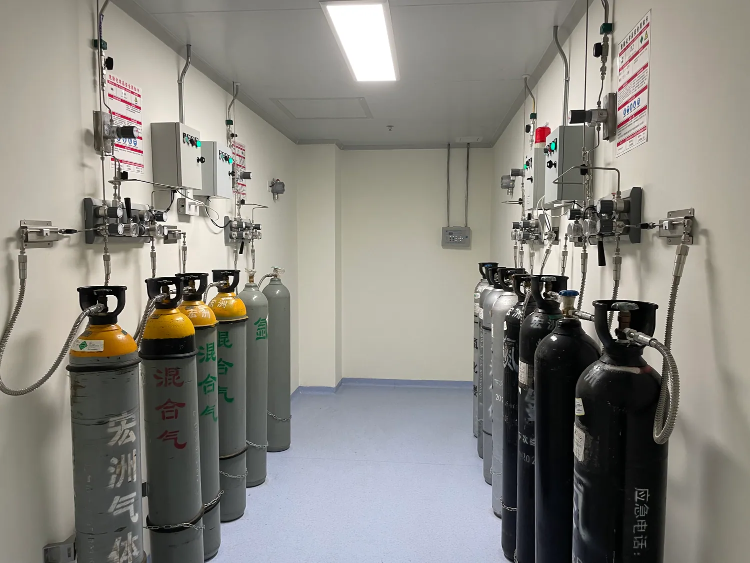
Cylinders may be placed in a dedicated room, a ventilated gas cabinet or another approved location. The decision is driven by the gas hazard, quantity, room design, access for changeout and the facility ventilation strategy. A remote cylinder source can reduce routine cylinder movement through occupied work areas, but it adds a distribution route and more interfaces to inspect. A local source can shorten the line, but it must fit the containment, ventilation and access requirements for that particular gas.
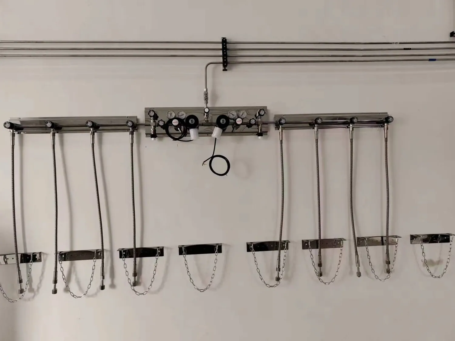
At the source, the engineer should identify cylinder restraint, compatible inlet connections, pressure indication, isolation points, regulator capacity, relief or vent paths where required and a controlled method for cylinder change. A manifold or automatic gas cylinder switchover for lab service may be justified when an interrupted supply would damage a test or instrument. Continuity alone is not enough: changeover logic, empty-cylinder indication, maintenance isolation and the behavior of each bank during a fault must be stated.
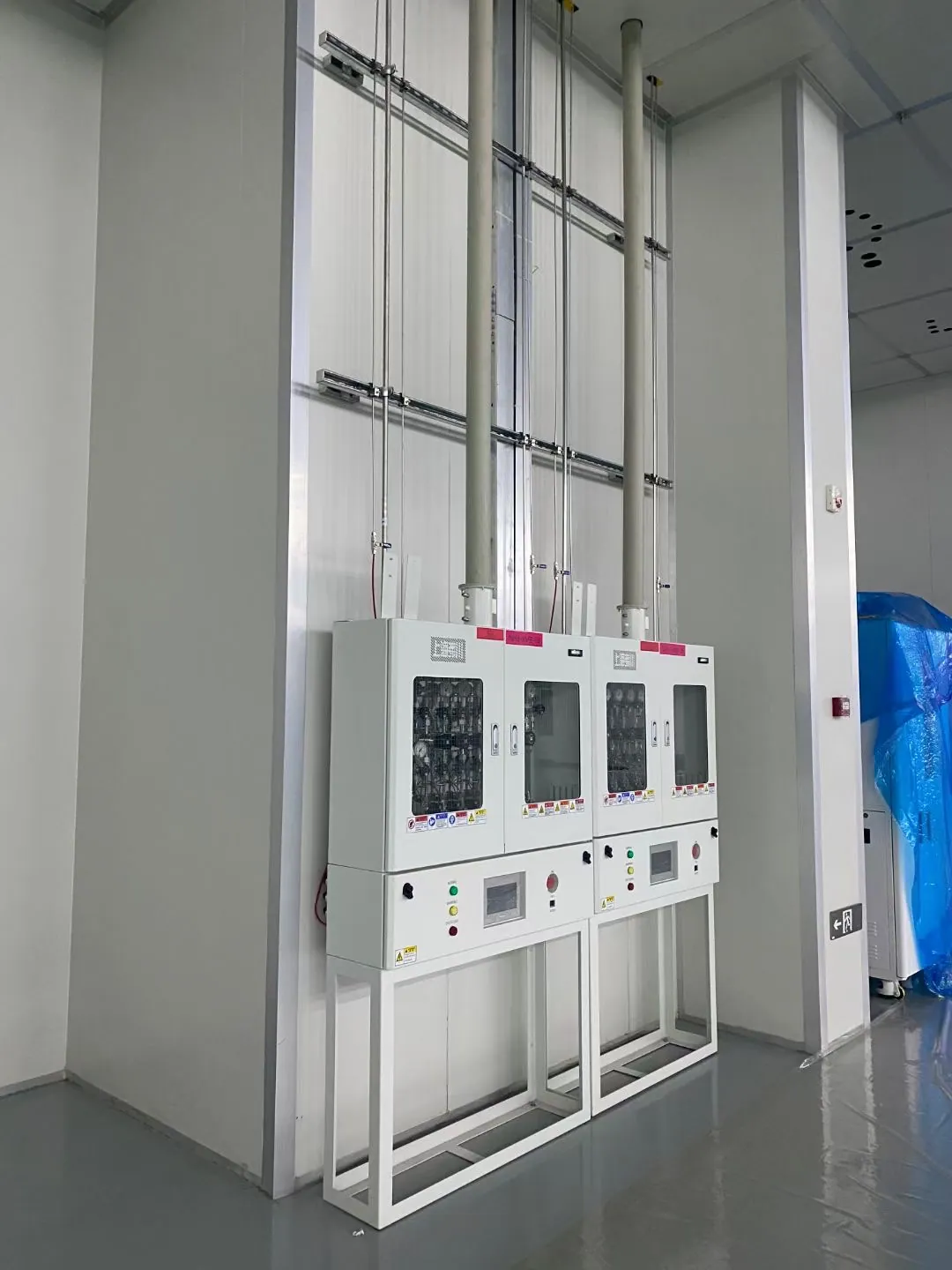
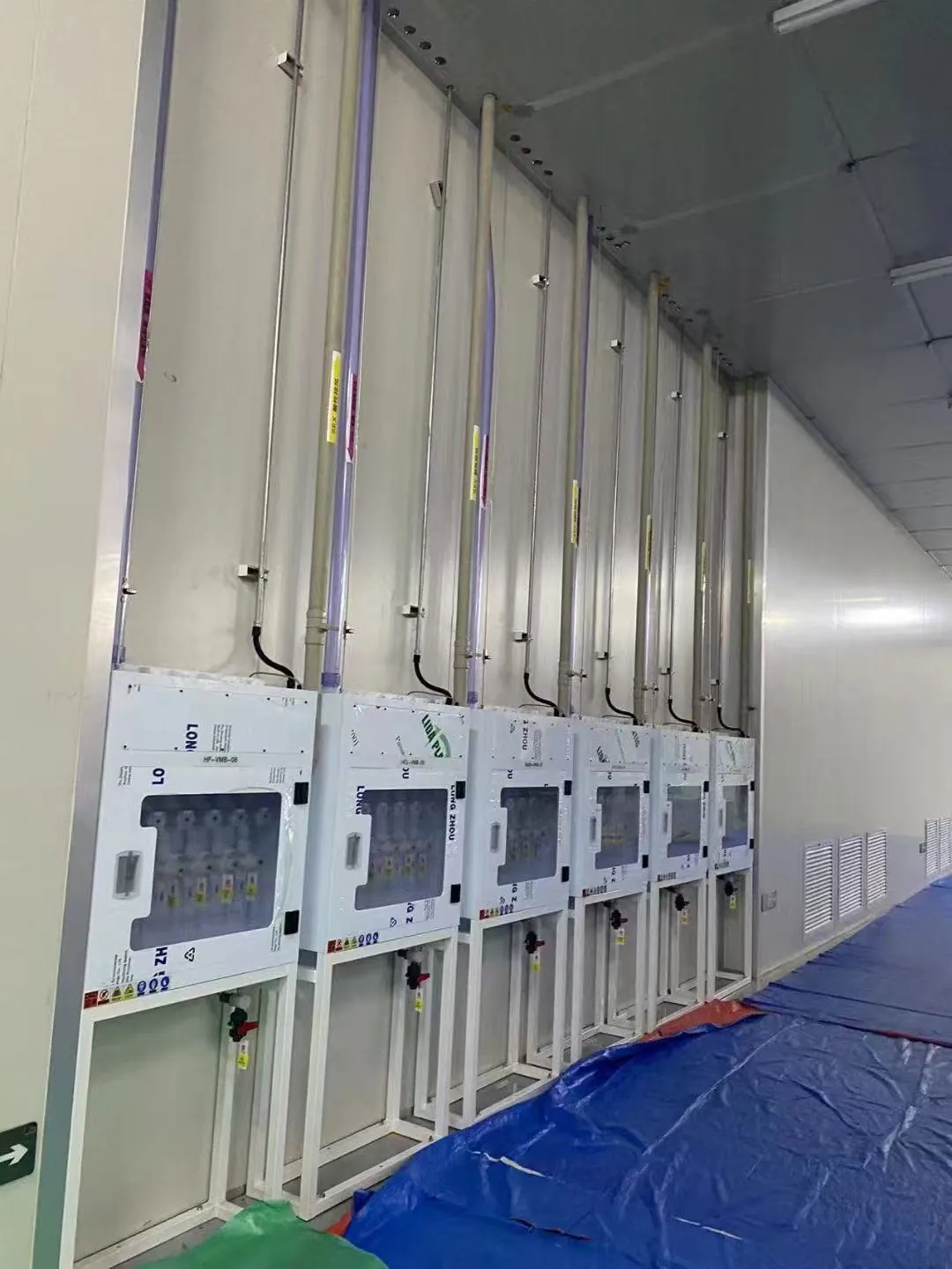
The photograph shows a cylinder-bank arrangement rather than a recommended configuration for every flammable gas. Site designers must verify gas segregation and the suitability of each cabinet, manifold and connection for the named gas. A generic high-purity manifold is not automatically an approved hazardous-gas source assembly.
03 / DISTRIBUTION
Trace the path from cylinder to instrument
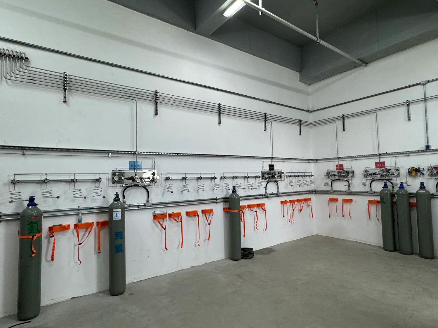
A laboratory gas distribution system has several pressure boundaries: cylinder pressure, regulated header pressure and the pressure needed at each instrument. The design should calculate simultaneous flow and pressure loss through the proposed line, regulator, valves, fittings and final hose or connector. This matters when a long route serves multiple instruments, when an instrument has a narrow inlet-pressure range or when the supply switches banks. Size and regulator selection should follow the duty, not the nominal size of an existing port.
The route should make the line identifiable and serviceable. Record where it crosses rooms or fire compartments, where it can be isolated, how it is protected from mechanical damage and how a technician can access connections for inspection. Use materials, seals and connection practices compatible with the named gas and pressure range. A 316L stainless-steel laboratory gas line may be appropriate in many systems, but its suitability is still a gas-specific engineering decision. Avoid hidden joints or unreviewed dead legs where a leak would be difficult to find.
The endpoint matters as much as the source. A point-of-use laboratory gas system can provide local pressure control and a clearly labeled shutoff near the instrument. Its position should work with the instrument connection, user workflow and emergency response. If several devices share a branch, document the consequence of one user closing or adjusting the branch. A clean drawing of the complete route is more valuable than a list of individual fittings.
04 / SAFETY INTERFACES
Coordinate detection, ventilation and automatic isolation
Gas detection is useful only when its sensing location, alarm logic and response have been designed for the actual release scenario. A detector near the source may not cover a remote terminal or a concealed route. Sensor technology must suit the gas and surrounding conditions, and the maintenance team needs a calibration and test plan. The design should explain who receives each alarm, whether it is local or centrally monitored, and how occupants know what action to take.
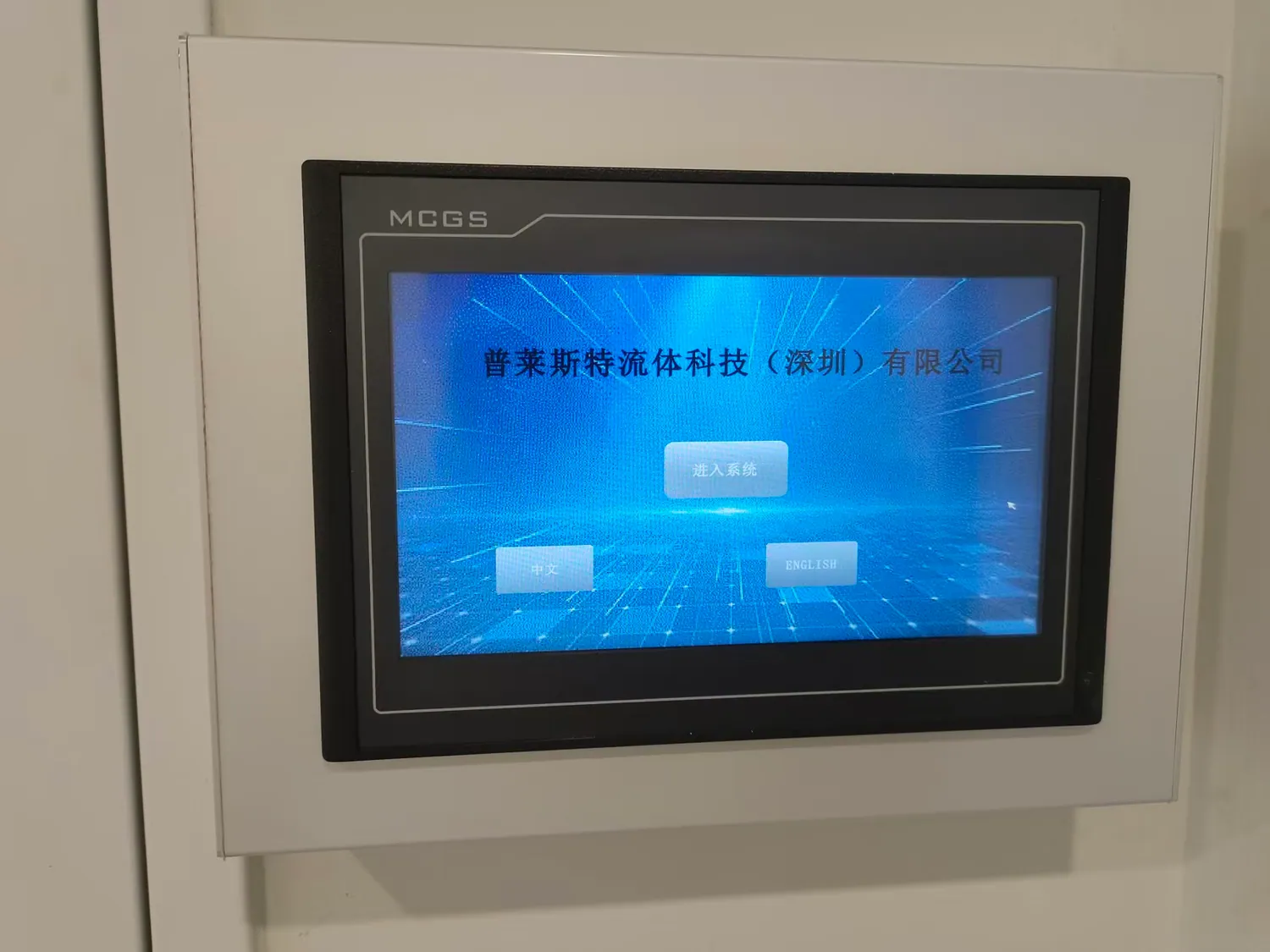
Ventilation, detection, source valves and emergency-stop devices may need to work together. For example, loss of cabinet exhaust can be a reason to stop gas flow in a hazardous-gas installation. The exact sequence must be reviewed by the project safety team and tested at commissioning. Make the control cause-and-effect matrix explicit: input, expected alarm, valve state, reset conditions and responsible operator. Do not assume that a visible warning light proves the gas path is isolated.
The building exhaust system is outside the gas panel but inside the safety problem. Confirm duct connection, exhaust monitoring, discharge route, make-up air and resilience requirements with the mechanical designer. The gas equipment supplier should provide interface information rather than silently claiming that a cabinet alone makes the room safe. See our exhaust and purge solution for the downstream boundary.
05 / OPERATIONS
Plan changeout, purge and maintenance before commissioning
Routine tasks often create the most frequent opportunities for air ingress or release. The source layout should let trained personnel identify the active supply, isolate the correct section and carry out a cylinder change without improvising connections. Where purging is required, the purge source, gas compatibility, vent destination and valve logic must be designed as part of the system. A generic instruction to “purge with nitrogen” is insufficient for every flammable gas, mixture or process.
Maintenance access also shapes the installation. Pressure regulators, detection heads, actuated valves and gauges need room for inspection or replacement. The design should show where a technician can depressurize or isolate a section and how the residual gas will be managed. Emergency isolation must remain accessible without requiring a responder to approach a suspected release. Labels should distinguish source, reserve bank, branch, outlet and control states.
Document the expected operating modes: normal supply, standby supply, changeout, purge, test, maintenance and shutdown. For each mode, note which organization owns the procedure. LGF Lab Gas Flow can support a component schedule and control-interface review, while the facility must approve the operating procedure, training and emergency plan for its site.
06 / ACCEPTANCE
Verify the assembled system, not only the parts
Factory certificates for regulators or valves do not demonstrate that the installed line is leak-tight or that the building interlock acts as intended. The acceptance plan should be agreed before construction. It may include material and connection verification, pressure and leak testing appropriate to the system, line identification, detector and alarm checks, simulated fault responses, and a record of the final settings. The selected methods and limits must come from the applicable design and the gas hazard assessment.
A practical handover package identifies the actual equipment and its location. Ask for an as-built schematic, component schedule, gas compatibility review, test records, detector calibration information, cause-and-effect matrix, maintenance instructions and training responsibilities. The package should show the interface to ventilation and any exhaust-treatment equipment. These records help a future technician understand the system after staff or experiments change.
The final review should compare the installation with the original gas-use schedule. Has another instrument been added? Has the mixture changed? Are spare outlets capped and labeled? Have changes to room ventilation altered the assumed protection? Treat future additions as management-of-change events rather than simply connecting another tube to a convenient header.
PROJECT DECISIONS
Questions that make the specification stronger
Hydrogen, acetylene and mixtures are different design cases
Hydrogen is commonly chosen for chromatography and energy research, while acetylene may serve an analytical flame and methane may be a process feed. Their physical behavior, supplier connections, use rates and approved protective measures differ. The gas schedule should therefore preserve the exact identity and mixture composition instead of replacing it with a generic “flammable” label. A mixture can change classification as its concentration changes; ask the supplier for the current safety data and have the facility safety team evaluate it.
Gas-specific review affects the likely release location, detector technology and placement, ventilation concept, compatible materials and acceptable source location. It also affects whether an instrument’s built-in shutdown can be relied upon and how a user recognizes a failed source. A drawing that shows only “H2 line” without concentration, pressure and source type leaves too much to interpretation. The project’s operating envelope should remain visible in the final schematic and maintenance file.
Specify the boundary between equipment and building controls
A gas supplier can provide a cabinet, manifold, valve actuator and local controller, while the building team provides the exhaust fan, duct, power, monitoring and emergency communication. The project must state where one package ends and the next begins. For every interlock, list the available contact or signal, its normal state, the action on fault and the test method. This is especially useful when different contractors install the gas equipment and the facility controls.
If an alarm is sent to a building management system, decide whether the building system is merely reporting a condition or is required to cause isolation. If a user can reset a controller locally, decide whether a ventilation or detector fault must be cleared first. These are design decisions, not optional settings to leave to the installer. A one-page interface schedule can prevent an expensive late-stage dispute over who supplied the cable, damper or control logic.
Use a fault table to compare supplier proposals
A procurement comparison should ask each bidder to describe the system state during loss of normal power, low exhaust flow, detector alarm, low cylinder pressure, regulator failure and emergency-stop activation. The table should show whether gas delivery stops, which bank remains available, what local and remote indication appears and how authorized personnel can restore service. Proposals that quote similar cabinets can behave very differently during the fault that actually matters.
The same table exposes assumptions about continuity. An automatic changeover may protect experiments from an empty cylinder, but it must not bypass a safety shutdown. A manual emergency stop should be placed where it can be used without approaching the suspected release. The location and response must be reviewed with the facility team. Ask bidders to supply a draft cause-and-effect matrix with the offer so the final configuration is reviewable before purchase.
Match documentation to the laboratory’s future changes
Research programs evolve. A new gas mixture, higher-flow instrument or room renovation can alter the accepted design basis. Mark the maximum intended service and unused connection points on the as-built drawings. Keep a log of the gas identity, source size, connected tools, safety settings and approved changes. This lets a future project engineer tell whether an addition fits within the original envelope or needs a new assessment.
The owner should also plan periodic verification. Detector calibration, cabinet airflow checks, valve function tests and line inspection should follow the approved maintenance plan and manufacturer instructions. A system that passed commissioning once can drift out of its intended state after a sensor is replaced or a ventilation setpoint changes. Records make protective features visible and help prevent a well-intentioned maintenance action from defeating an interlock.
What a useful enquiry to LGF Lab Gas Flow should contain
Send a room drawing, gas and mixture list, safety data, cylinder connection details, instrument pressure and flow requirements, expected simultaneous use and preferred source location. State whether the facility already has approved cabinet exhaust, gas detection and emergency-power provisions. A photograph of the intended wall can help locate panels and access points, but dimensions and a marked-up plan are still needed for engineering.
LGF Lab Gas Flow can then help develop a scope for source regulators, gas manifolds, distribution components, point-of-use controls and monitoring interfaces. The quotation should separate equipment supply from installation, building ventilation and permit responsibilities. That separation lets your facilities and safety teams review a concrete system boundary before committing to hardware.
Example: one hydrogen instrument versus a shared research suite
Consider a single chromatograph that uses hydrogen in an existing analytical room. The questions begin with the source type and approved location, the instrument’s flow and pressure, local containment requirements and a short, identifiable route. The project may have one use point, but detector and ventilation decisions still depend on the gas and room. A site survey should confirm whether an existing exhaust connection is suitable and whether the instrument itself provides any verified protective functions.
Now consider a research suite with several hydrogen users and changing test rigs. Simultaneous demand, source continuity, branch isolation, alarm distribution and management of future connections become more important. A shared source can be efficient, but each branch should have a named destination and a documented impact on other users. These examples show why neither a “small system” nor a “central system” is a safety specification by itself.
Questions to ask before signing off a layout
Can a technician reach every source valve, detector and regulator for maintenance? Is the suspected leak area avoidable when an emergency stop is used? Does the route cross a room or enclosure not shown on the schematic? Which device isolates gas when exhaust is unavailable, and how will that response be tested? The design team should be able to answer each question with a drawing, schedule or control narrative.
Ask also who owns post-occupancy changes. If an experiment introduces a new mixture or an instrument is moved, the owner needs a process to review gas classification, pressure loss, detector coverage and source capacity. The final design should make those checks possible. An obscure installation with no as-built information is expensive to extend safely.
Related equipment and the next decision
The equipment scope may include a laboratory specialty gas cabinet, a manifold or changeover system, pressure regulators, isolation valves and a gas monitoring interface. These are not interchangeable safeguards. Each item must have a defined role in the project hazard assessment and work with the surrounding building systems.
If your team has only a partial gas schedule, start with the room plan and the instrument requirements. LGF Lab Gas Flow can help identify missing source and distribution information for a technical discussion. Final safety approvals, local code compliance, exhaust design and operating procedures remain with the responsible qualified professionals.
START A TECHNICAL DISCUSSION
A useful flammable-gas project brief
Useful quotations begin with a clear operating envelope and a visible division of responsibility. Send the available information; unresolved items can be identified during review.
- Gas name and mixture composition, cylinder size, quantity, supplier connection and safety data.
- Each instrument’s pressure, flow, simultaneous demand, duty cycle and location.
- Proposed source room or cabinet, cylinder-change route and building ventilation information.
- Desired monitoring, alarm recipients, emergency isolation and control-system interfaces.
- Current drawings, applicable local approvals and who signs off the final hazard assessment.
FREQUENT QUESTIONS
Questions teams ask before selecting equipment
Does every flammable laboratory gas require a gas cabinet?
The answer depends on the specific gas, quantity, location and applicable local requirements. A project hazard review determines whether a ventilated cabinet, dedicated source room or another approved arrangement is appropriate.
When is automatic changeover useful?
It is useful when a loss of supply would interrupt critical work or damage an instrument, provided the changeover and fault states are designed, maintained and understood.
Can one detector protect the entire route?
A detector only monitors the conditions at its sensing location. Source, route and endpoint release scenarios should be assessed before deciding the number and placement of sensors.
What should be submitted for a quotation?
Send the gas list, cylinder details, room and instrument layout, pressure and flow requirements, ventilation information and desired control interfaces.
TALK TO LGF Lab Gas Flow
Turn the gas list into a reviewable system scope.
Share the room plan, gases, instrument requirements and available building interfaces. We can help define the source, control and distribution equipment for your project.