
LGF Lab Gas Flow / LABORATORY GAS SOLUTIONS
Centralized Laboratory Gas Supply Systems
A coordinated route from the gas source to every instrument. Explore the decisions behind a central laboratory gas supply system: gas schedules, cylinder management, pressure control, distribution, point-of-use connections and safety interfaces.
THE COMPLETE SYSTEM
What is a centralized laboratory gas supply system?
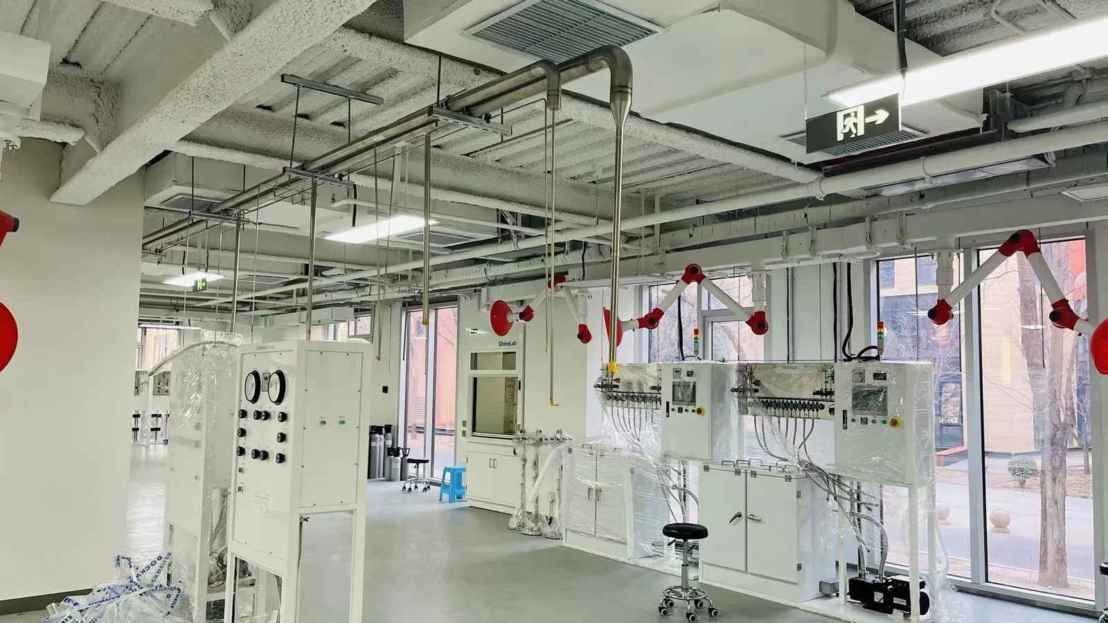
It is a planned gas-delivery network that moves one or more gases from a controlled source area to multiple laboratory instruments or workstations. The system may include cylinder banks, gas cabinets, changeover manifolds, primary regulators, separate distribution lines, isolation valves, local pressure-control panels, monitoring and purge or exhaust interfaces. Each gas remains on a deliberately specified path.
Central supply is often considered when several instruments use the same gas, when cylinders beside benches create handling or space problems, or when a facility needs a defined way to manage source changes and access. It is not automatically the right answer for every lab. A single instrument with low, intermittent demand may be better served by a local cylinder or a compact modular panel. The decision depends on the gas, usage pattern, building layout, risk assessment and total operating effort.
For a new or renovated facility, the key question is not simply “How many outlets?” It is whether the required gas purity and delivery pressure can be maintained at the instrument under normal and peak demand, while allowing cylinder changes, maintenance and emergency response to be handled safely. The rest of this page shows how to turn that question into a practical specification.
SOURCE-TO-INSTRUMENT ARCHITECTURE
Six decisions along the gas path
This is a planning model, not a universal piping diagram. Equipment order, protective devices and operating sequences must be defined for the specific gas service and facility.
FIT FOR THE LABORATORY
When does centralized supply make sense?
Centralization is most useful when the benefit of a managed source and shared distribution outweighs the extra pipework, commissioning and upkeep. Multiple instruments using nitrogen, argon or helium across rooms are a common example. Moving cylinder changes to a designated source area can reduce interruptions in occupied workspaces and make gas inventory easier to manage. A standby bank may help applications that cannot tolerate a source interruption, provided the changeover and alarm sequence are specified correctly.
Research facilities often change their instruments and room assignments. A planned distribution backbone can support future outlets, but spare capacity should be deliberate rather than guessed. It affects tube sizing, pressure drop, source capacity and where isolation is placed. For high-purity gas, every additional joint, dead leg and handling step may also create a contamination opportunity; expansion plans should be balanced against the actual purity target.
A compact laboratory with one or two use points may need a simpler arrangement. Likewise, a gas with unusual hazards may call for dedicated containment, monitoring and exhaust rather than a generic shared manifold. The project should compare alternatives by operating pattern, risk, maintainability and documented life-cycle cost rather than assume that “central” always means safer or cheaper.
DESIGN INPUTS
Build the gas and instrument schedule first
The best way to avoid a mismatched laboratory gas distribution system is to collect demand at each point of use before choosing regulators or tube sizes. A useful schedule identifies the gas and grade, each instrument’s specified inlet conditions, normal and peak consumption, operating hours, permitted pressure variation and likely future changes.
| Input | What to record | Why it changes the design |
|---|---|---|
| Gas identity and quality | Gas or mixture, purity grade, moisture or particle limits where specified | Determines compatible wetted materials, cleaning and separation needs |
| Instrument demand | Required pressure and flow at each connection, including simultaneous peak use | Sets regulator capacity, line size and allowable pressure drop |
| Source and continuity | Cylinder size, bank arrangement, refill frequency and allowable interruption | Guides manifold capacity and manual or automatic changeover |
| Location and route | Source room, rooms served, route length, access and future outlets | Shapes zoning, isolation, maintenance access and installation method |
| Hazard controls | Gas hazards, ventilation, detection, purge, exhaust and shutdown interfaces | Defines the facility review and controls beyond pressure regulation |
| Handover needs | Drawings, labeling, test records, training and maintenance responsibilities | Makes the installed system identifiable and maintainable |
A gas schedule is a project input, not a finished design. Final pressure, flow, material and safety choices require review by qualified personnel for the destination site and applicable requirements.
FUNCTIONS & EQUIPMENT
How the main components work together
1. Gas source, cabinet and manifold
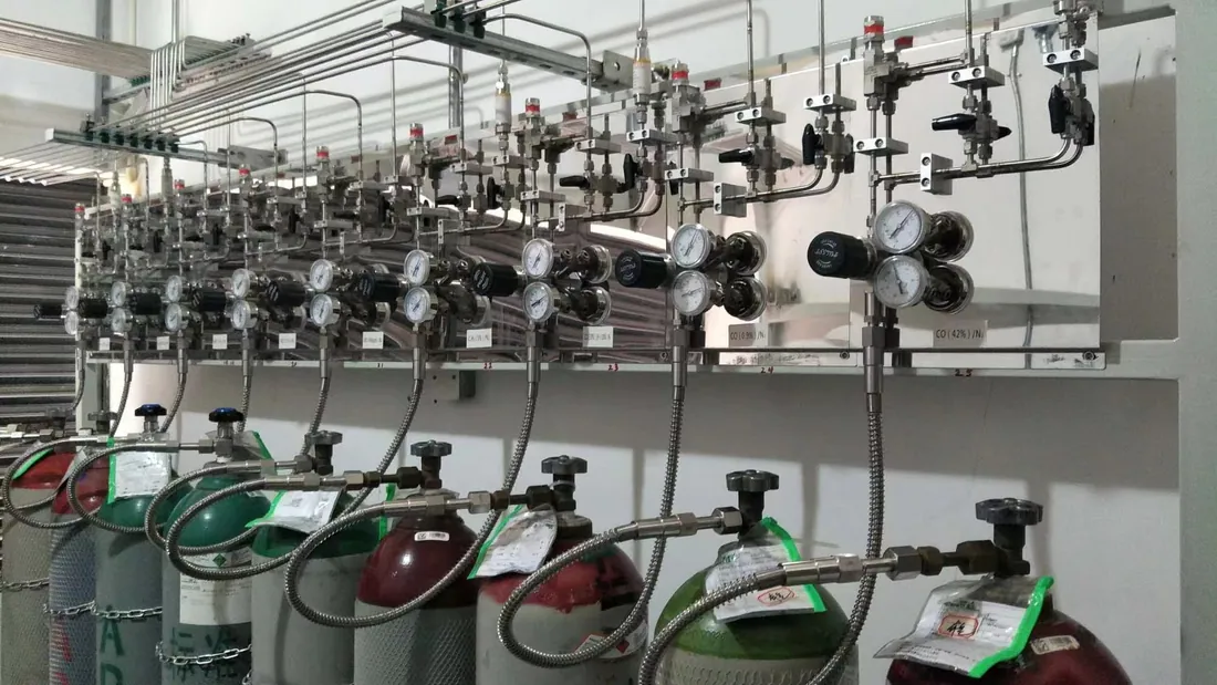
The source may be individual cylinders, grouped cylinder banks or another facility-approved supply. The gas list determines whether an open source station, a dedicated storage room or a ventilated specialty gas cabinet should be considered. Hazardous gases require a site-specific assessment of containment, ventilation, detection and shutdown interfaces; an equipment enclosure by itself does not resolve the whole risk.
A gas manifold and changeover assembly connects source banks and controls which one feeds the line. Manual changeover relies on an operator. Semi-automatic and automatic arrangements can transfer supply according to their control design, but the reserve bank, alarm signal and replacement procedure still need active management. The correct arrangement depends on how much interruption the instruments can tolerate and how often cylinders are changed.
Where cylinders contain high-purity or reactive media, the source connection, purge sequence and connection standard become part of the purity and safety plan. The team should document what happens when a cylinder is replaced, a bank is depleted or a source valve is closed.
2. Primary and local pressure control
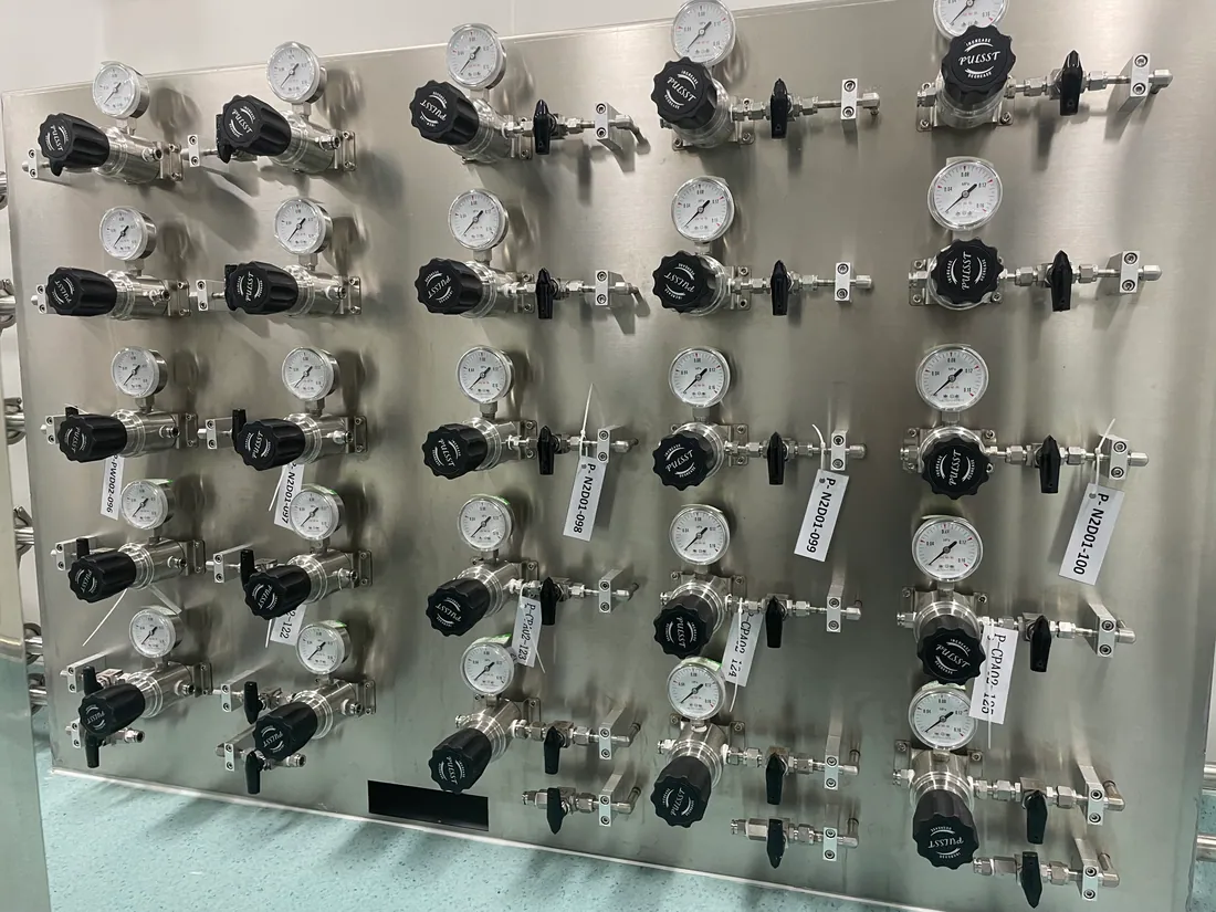
Cylinder pressure is usually too high and too variable to deliver directly to an instrument. A primary regulator or panel establishes a controlled distribution pressure. A second control stage near the instrument can then match the equipment’s inlet requirement. This division can make it easier to serve different instruments, but only after the available source pressure, line losses and simultaneous demand have been checked.
UHP and high-purity regulators should be selected for the actual media, pressure range, flow, wetted materials and connection type. “Two-stage” is a design concept, not a promise of perfect stability: regulator performance, source depletion and downstream demand must be assessed together. Gauges or transmitters may be used at selected points so operators can distinguish a low cylinder bank from a downstream restriction or local adjustment issue.
A regulated line should also have defined isolation and relief strategies appropriate to its service. Their locations and set points belong in the engineered design and operating documents, not in a generic website diagram.
3. Distribution lines, valves and connections
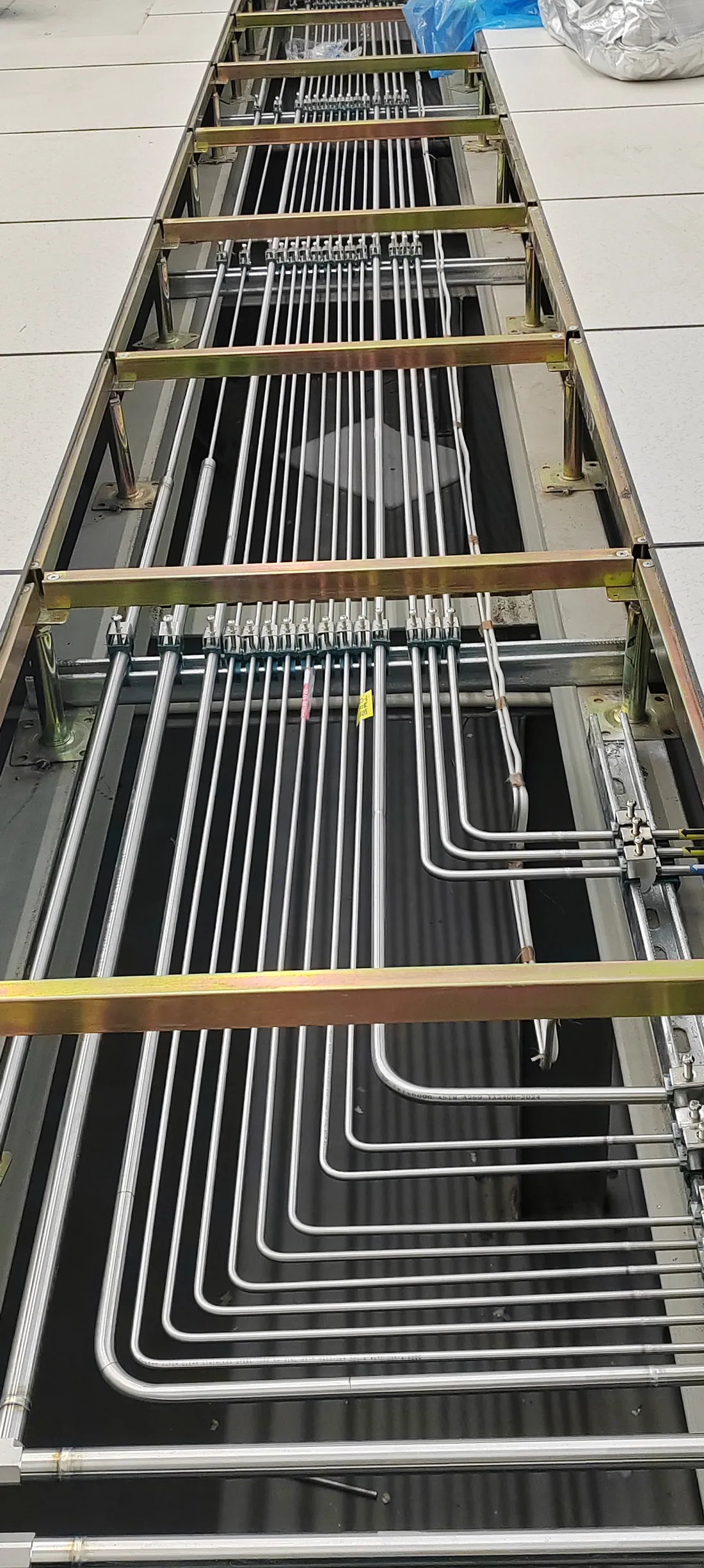
The laboratory gas piping system carries each gas from its source to the required rooms and outlets. Pipe or tube size must account for peak flow, route length, fittings and the pressure remaining at the farthest point of use. Gas compatibility and cleanliness may be just as important as pressure rating. A route that works for a general utility gas may not suit an ultra-high-purity, corrosive or highly reactive service.
For some high-purity applications, specified stainless-steel tubing and fittings are appropriate, while other gases and facilities may use different approved materials. The specification should state the required material grade, surface condition, cleaning, joining method and acceptance criteria. Neither 316L nor any connection style should be treated as universally suitable.
Diaphragm valves and fittings can support isolation and clean connections at panels, branches and instrument interfaces. Zone valves should be accessible and clearly identified so that maintenance or emergency response can isolate the intended section without guessing which line is which. Routing should also make future inspection possible and avoid unplanned joints or inaccessible dead spaces.
4. Point of use and monitoring
The final instrument connection is where the specified gas quality, pressure and flow have to arrive. A point-of-use panel may combine local isolation, final regulation, a gauge and a suitable outlet connection. The panel layout should make routine operation clear without exposing users to unnecessary source controls. Outlet labeling and connection compatibility matter because different instruments can sit close together on the same bench.
Monitoring and safety interfaces may track source and line pressure, changeover status, gas detection, cabinet exhaust status or other project-defined conditions. Alarm thresholds, recipients and response actions should be decided with the facility team. A pressure gauge alone is not a gas-leak detector, and monitoring without a response plan is incomplete.
For hazardous gases, the design may need ventilation, purge, exhaust treatment and emergency isolation coordinated with building systems. For inert gases, oxygen-deficiency risk may still require evaluation. The exact measures differ by gas, quantity, occupancy and local rules.
ENGINEERING TRADEOFFS
The choices that most affect system performance
Purity at the point of use
A bottle label describes the source gas; it does not by itself prove the quality delivered after regulators, connections and tubing. Review wetted materials, internal cleanliness, moisture exposure during cylinder exchange, potential permeation, dead legs and the test method required by the application. An analytical instrument may have a different tolerance for moisture or particles than a general utility outlet. Document the target at the instrument and the evidence needed to confirm it.
Pressure and simultaneous demand
Sum realistic peak use, not just average consumption. Check the minimum source condition, primary regulator droop, line losses and the pressure required at the most demanding outlet. An undersized route can starve instruments when several run together; an oversized route can add cost and internal volume. If demand varies widely, branch zoning or local control may help. The final values require engineering calculations and equipment data.
Continuity versus complexity
A standby bank and automatic changeover can reduce interruption during source depletion, but they add controls, maintenance and a need to know which bank is active. A manual manifold may be sufficient for intermittent work. The specification should define the acceptable interruption, alarm timing, reserve capacity and operator procedure before selecting a changeover type.
Safety and local requirements
Flammable, oxidizing, toxic, corrosive and inert gases do not share a single safety design. Source location, separation, cabinet or room ventilation, detector placement, alarm response, purge destination and emergency isolation must be evaluated for each service. Applicable codes and approvals depend on the project location. An early review with the facility safety team can prevent a late redesign of the gas route.
Maintainability and expansion
Leave safe access to cylinders, regulators, valves and test points. Label lines and outlets so maintenance can identify the gas and isolation boundary. Record spare capacity only where the business case and design allow it; “future proofing” without a defined load can compromise today’s performance or budget. An as-built drawing and operating sequence make later changes much easier to assess.
Testing and acceptance
Define acceptance evidence before installation begins. Depending on the service, the project may call for pressure testing, leak checks, cleanliness or purity verification, functional checks of changeover and alarms, and documented commissioning. The test medium, limits, hold times and responsibility must be project-specific. Passing one leak test does not verify every purity or control requirement.
CONFIGURATION EXAMPLES
Three common starting points
These examples show how the same source-to-instrument framework changes with the laboratory. They are discussion aids, not ready-to-install specifications.
Several instruments, routine inert gases
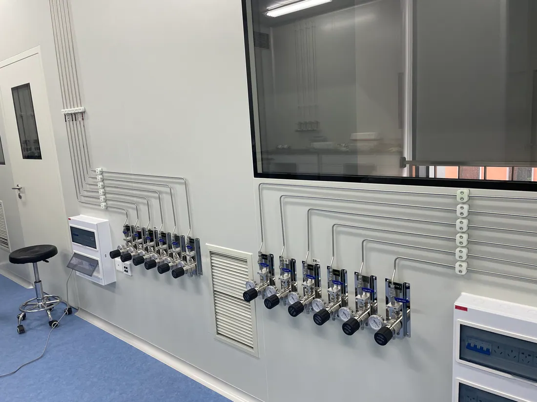
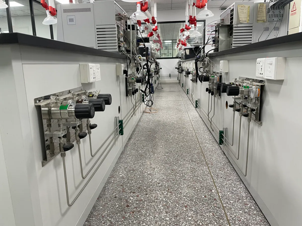
A shared nitrogen or argon line may serve instruments in several rooms from a managed cylinder source. The early questions are combined peak demand, source replacement frequency, route length and whether instruments need different local pressures. A bank manifold, distribution isolation and labeled point-of-use panels may form the core arrangement.
Clean delivery with documented interfaces
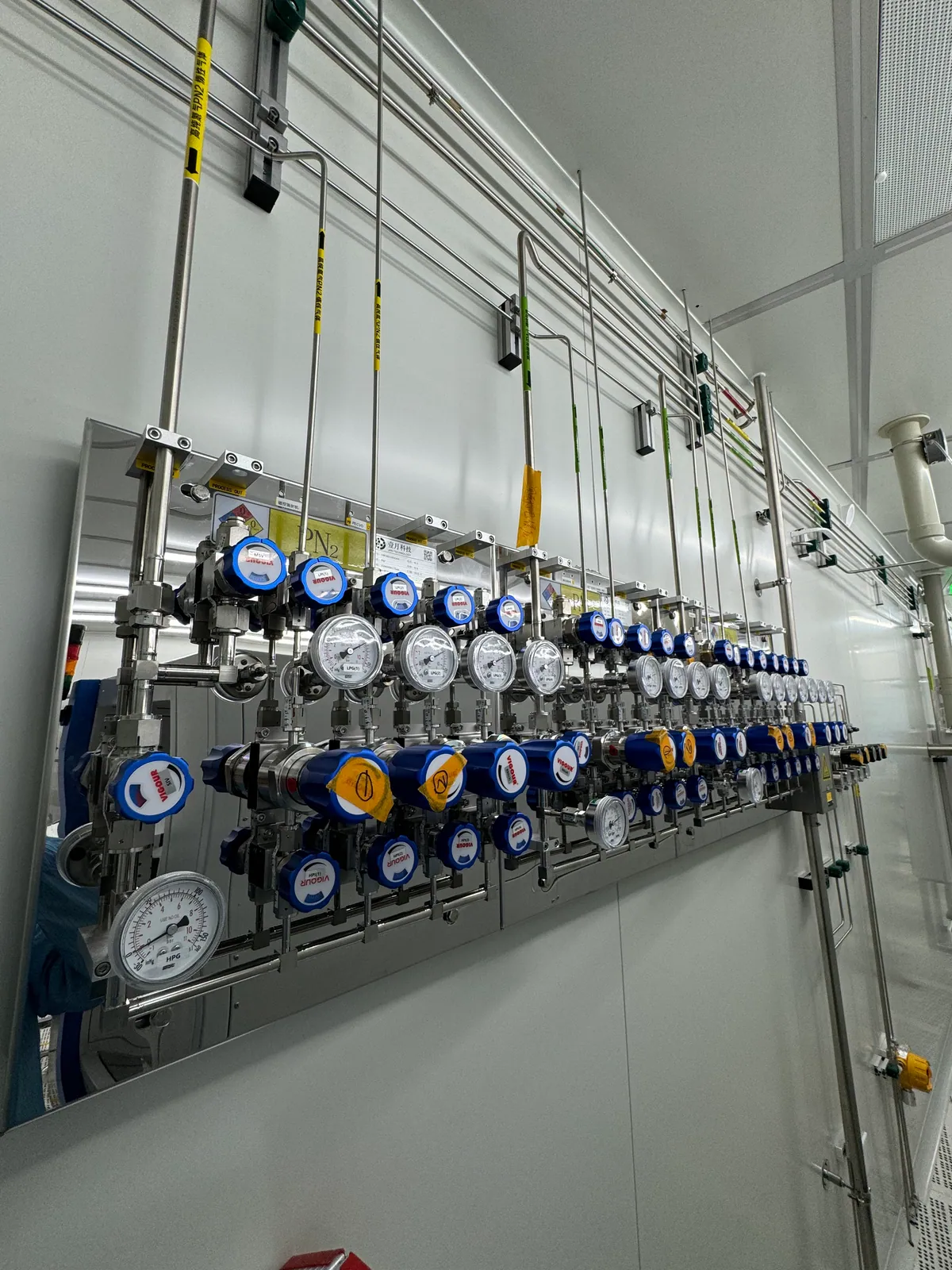
A research laboratory may require a tighter gas quality specification at an analytical instrument. The team should review source grade, regulator and valve wetted surfaces, connection practice, tubing cleanliness, purge method and acceptance test together. A nominally high-purity cylinder cannot compensate for an unsuitable downstream path.
Containment and coordinated response
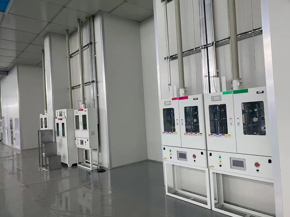
For a flammable or corrosive service, the source area and gas path need a specific hazard review. Cabinet or room ventilation, detection, emergency isolation, purge and exhaust interfaces may be required. The facility’s safety and engineering teams should define the sequence and applicable local requirements before equipment is selected.
FROM BRIEF TO HANDOVER
A practical project sequence
Confirm the use case
Collect the gas and instrument schedule, purity and pressure needs, source location, laboratory plans and target project date. Identify who owns the gas supply, facility systems and safety approval.
Compare architectures
Assess central versus local supply, cylinder-bank strategy, pressure stages, routing, zoning and any dedicated hazardous-gas path. Record why the preferred layout fits the operating pattern.
Specify interfaces
Define equipment boundaries, materials, connection standards, controls, power, ventilation, alarm contacts, purge and exhaust destinations. Confirm who supplies and installs each item.
Review and build
Approve drawings and component schedules before procurement. Coordinate the route and access with other building services. The installation method and safety controls follow the approved local design.
Verify and document
Perform the agreed pressure, leak, functional and cleanliness checks. Hand over as-built drawings, labels, operating steps, maintenance points and records needed by the facility.
LGF Lab Gas Flow can discuss components and engineered assembly options. The exact design, installation, inspection and approval scope must be confirmed for each project and jurisdiction.
PROCUREMENT CHECKLIST
What to send for a useful first review
Even an early-stage inquiry becomes more productive with a few concrete inputs. Send a simple list rather than wait for perfect drawings. We can identify missing decisions and discuss what belongs in the component quotation or broader system scope.
- Gas names, mixtures and required purity grades.
- Instrument list with inlet pressure, flow and connection details.
- Number of current and planned use points, rooms and floors.
- Cylinder size, estimated consumption and continuity requirement.
- Site location, layout drawing and preferred source location.
- Known ventilation, detection, purge or exhaust requirements.
- Requested deliverables: components, assemblies, drawings, testing or other support.
Where information is unknown, mark it as “to be confirmed.” This is more useful than choosing a regulator or pipe size from a generic chart. Keep the facility engineer, safety representative and instrument owner involved as the design develops.
FREQUENT QUESTIONS
Questions buyers ask before specifying a central system
Is centralized supply always better than cylinders at each bench?
No. It can improve source management for repeated or shared demand, but it adds distribution length, interfaces and commissioning work. Compare the real cylinder-handling burden, instrument continuity need, gas hazard, layout and total cost. A small lab may be better served by a modular source or local panel.
Will an automatic manifold guarantee uninterrupted gas?
It can reduce interruption during a planned bank transfer when correctly sized and operated. It cannot replace a full reserve bank, an appropriate alarm response or maintenance. The acceptable interruption, reserve capacity and changeover sequence should be specified before purchase.
Is 316L stainless steel required for every gas line?
No single material fits every gas, purity requirement and jurisdiction. Stainless steel is often considered for demanding high-purity paths, but material grade, surface finish, cleaning, joining and compatibility must be specified together. Other services may use different approved materials.
How is gas purity protected through the distribution path?
Start with the purity required at the instrument. Then review source grade, compatible wetted parts, cleaned tubing, connection integrity, cylinder-change and purge procedures, and the agreed verification method. The delivered quality depends on the complete route, not only one UHP regulator.
What is included in a system quotation?
That depends on the project boundary. A quotation might cover components, a source manifold, a gas cabinet, an assembled panel or a wider coordinated package. Drawings, site installation, testing, commissioning and local approvals should be listed explicitly so buyers and suppliers are comparing the same scope.
Which safety standard applies to my laboratory?
There is no single worldwide rule that covers all gases and sites. The gas properties, quantities, building use and jurisdiction determine applicable requirements. Have the facility engineer and local safety authority review storage, ventilation, detection, isolation, exhaust and acceptance criteria before approving the design.
PLAN A LABORATORY GAS SYSTEM
Start with your gas list and instrument requirements.
Tell LGF Lab Gas Flow what the laboratory needs to supply, where the instruments are located and what is already known about purity, pressure, flow and safety interfaces. We can discuss a suitable component and system scope for your project.