
LGF LAB GAS FLOW / PROJECT CASES
Optical Fiber Production Specialty Gas Supply
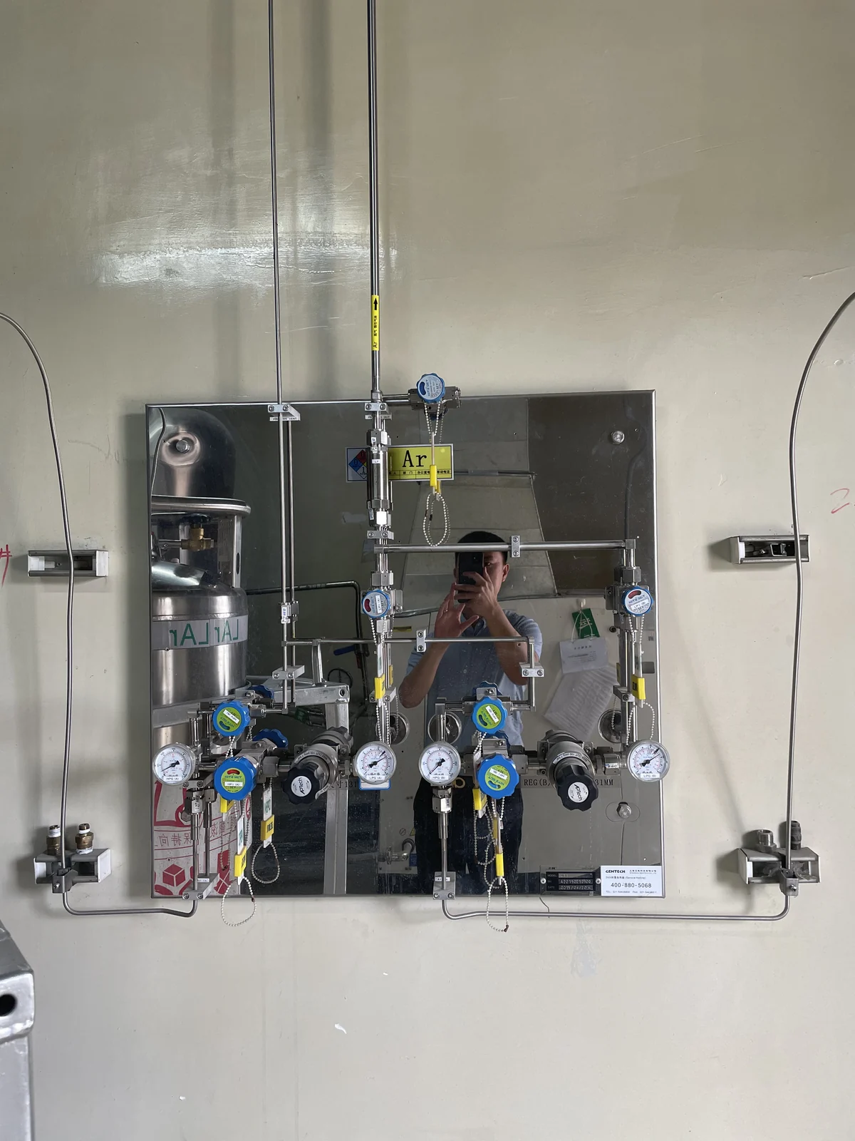
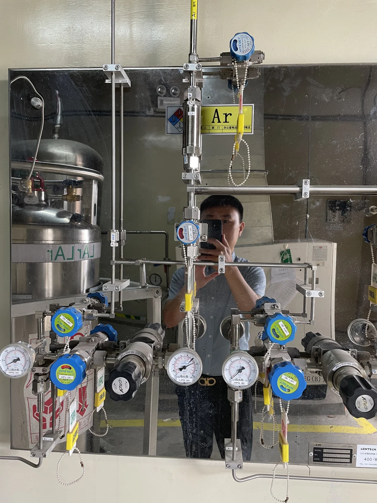
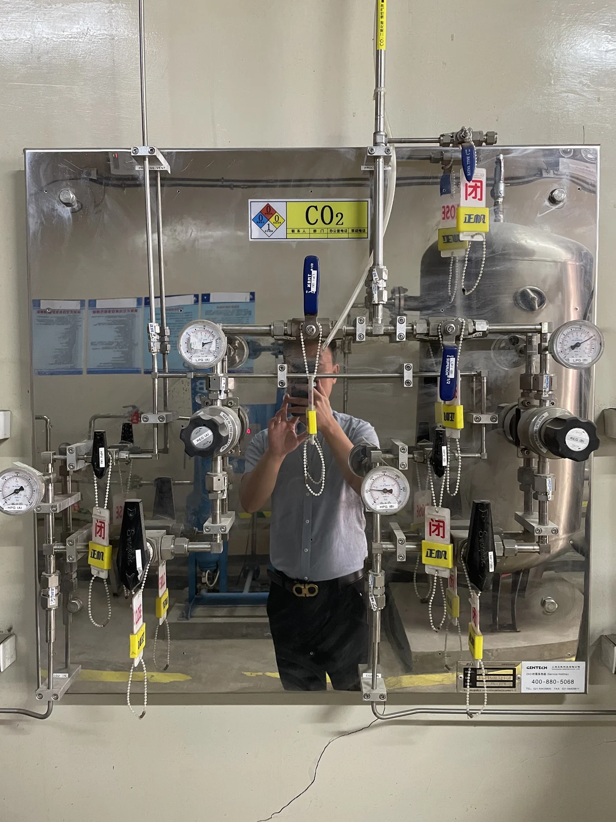
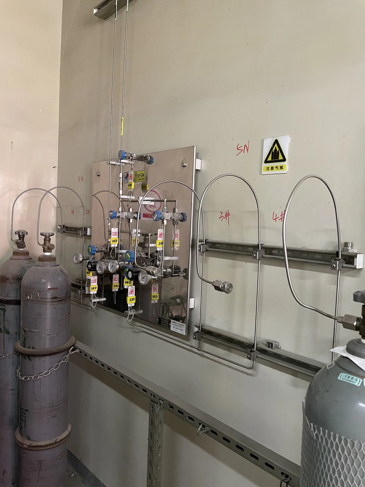
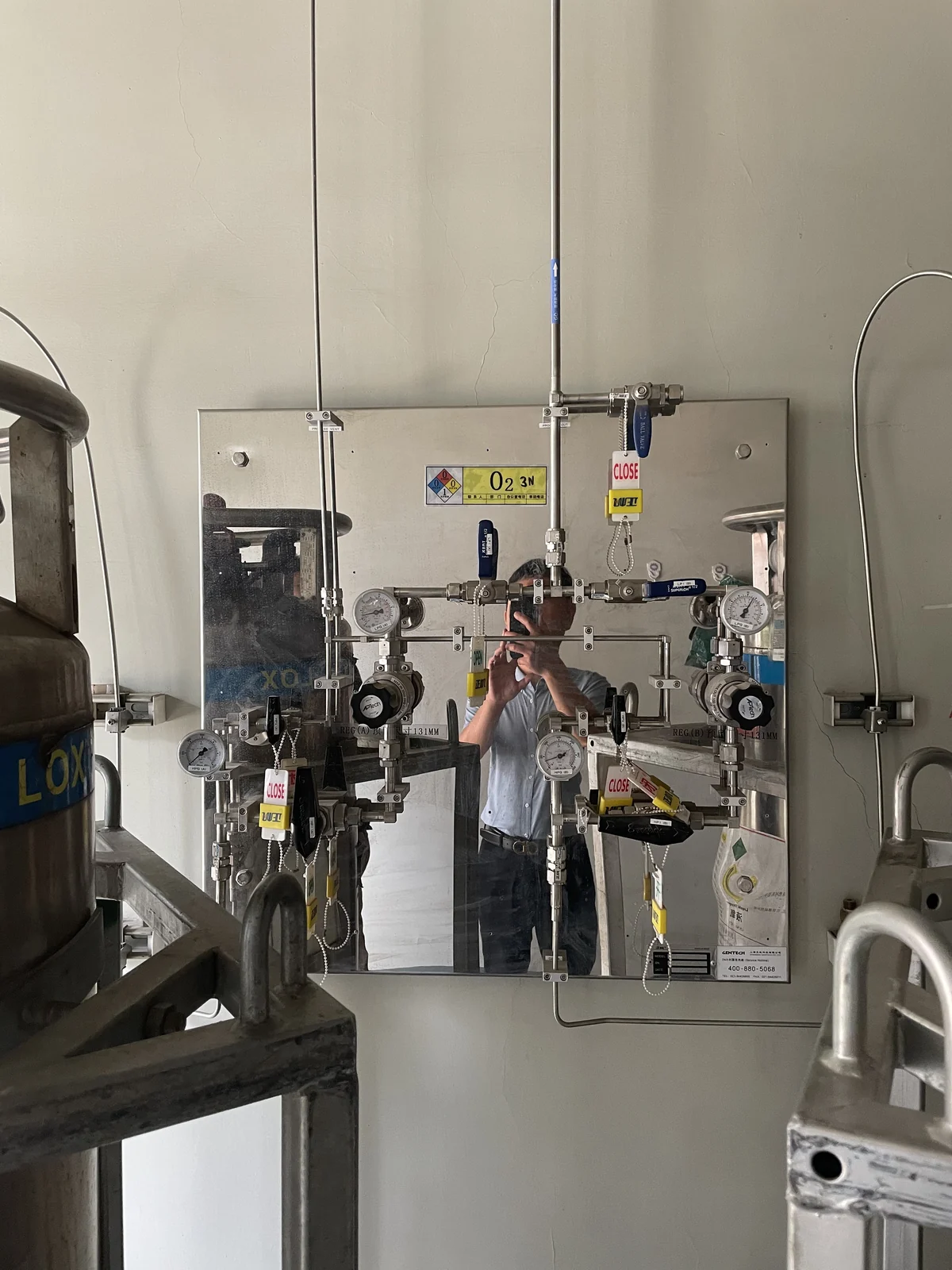
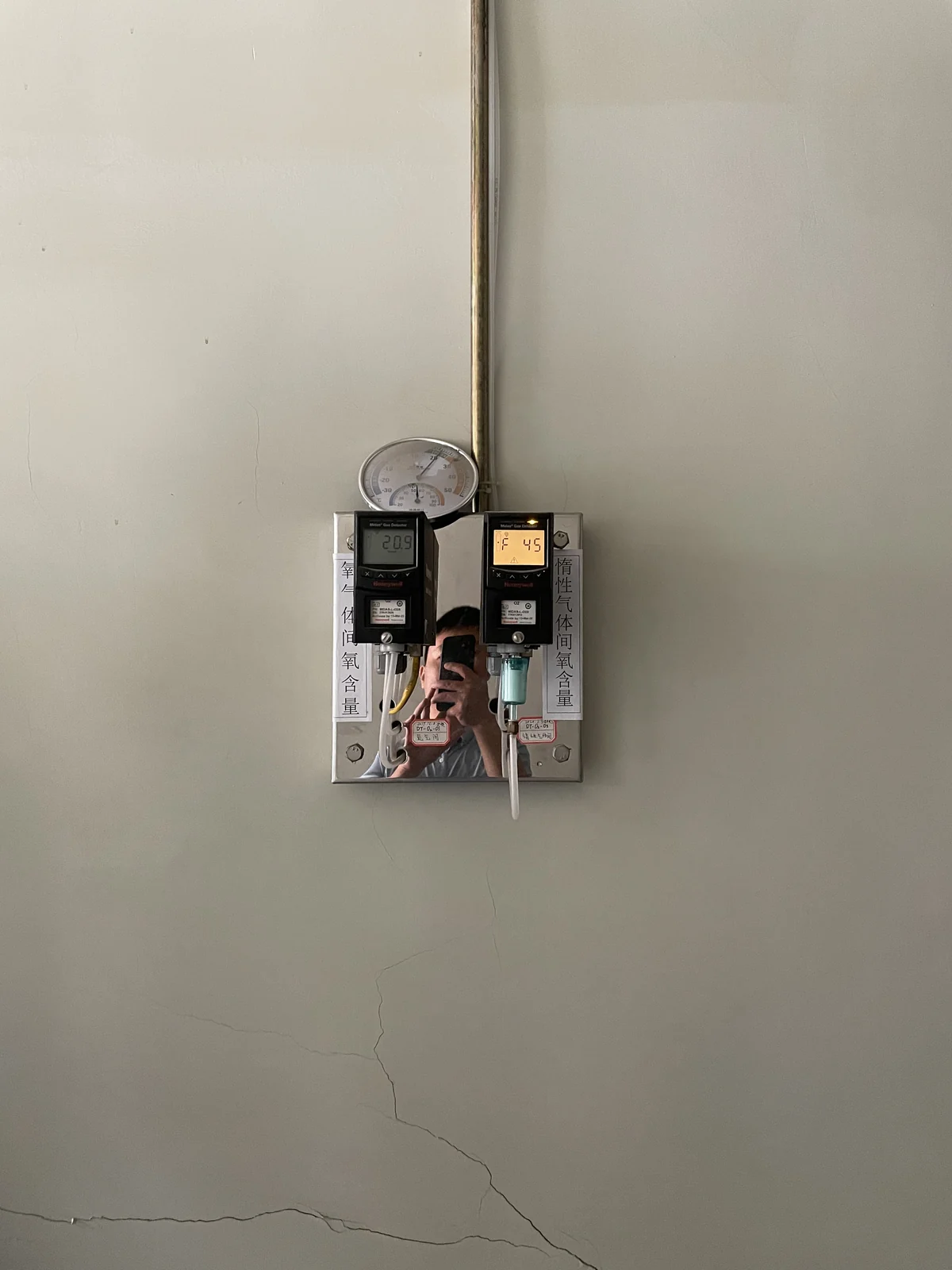
Installed regulators and pipework illustrate the source-to-equipment path in an optical-fiber production setting. The images do not reveal recipes, gas grades, setpoints or production results. Those facts belong in the owner’s process brief.
AN ILLUSTRATED PROJECT REVIEW
From visible installation to a clear engineering brief
For this optical fiber production setting, the engineering brief should make stable process gas delivery measurable through the gas schedule, source arrangement and point-of-use requirements.
For a project of this kind, the next step is to align the gas list, equipment inlets, facility rules and planned operating pattern. The photographs document visible hardware and routes; they do not certify gas identity, pressure rating, cleanliness, hazard controls or acceptance results. The sections below set out the questions to resolve in the project brief.
01 / PROJECT REVIEW
Build a tool gas matrix
Record gas identity, grade, inlet pressure, normal and peak flow and operating states for each machine. The matrix clarifies when a shared source is suitable and when a dedicated branch is needed.
For this optical fiber production setting, the final choice should be checked against the actual gas schedule, equipment data and approved site procedures. Record the decision on the source-to-outlet drawing so future maintenance or equipment changes can be reviewed without guessing from the installed hardware.
02 / PROJECT REVIEW
Keep control points accessible
Place regulator panels and isolation valves where their labels can be checked against the equipment schedule. Source enclosure, ventilation and alarm interfaces need a site-specific gas-hazard review.
For this optical fiber production setting, the final choice should be checked against the actual gas schedule, equipment data and approved site procedures. Record the decision on the source-to-outlet drawing so future maintenance or equipment changes can be reviewed without guessing from the installed hardware.
03 / PROJECT REVIEW
Protect line identity
Document supports, penetrations, joints and branch destinations before installation. For high-purity duties, specify material, cleaning and connection requirements for the entire path, including the final tool fitting.
For this optical fiber production setting, the final choice should be checked against the actual gas schedule, equipment data and approved site procedures. Record the decision on the source-to-outlet drawing so future maintenance or equipment changes can be reviewed without guessing from the installed hardware.
04 / PROJECT REVIEW
Define acceptance evidence
Agree on inspection, line identification, leak testing and any cleaning or purge records in advance. Update the as-built route when field conditions change.
For this optical fiber production setting, the final choice should be checked against the actual gas schedule, equipment data and approved site procedures. Record the decision on the source-to-outlet drawing so future maintenance or equipment changes can be reviewed without guessing from the installed hardware.
PROJECT DECISION NOTES
What should be agreed before procurement
Gas and equipment schedule
Provide gas identity and grade, normal and peak demand, inlet pressure limits, connection details and future expansion plans for every destination. This schedule prevents a proposal from treating unlike services as one generic line.
Facility interfaces
Identify source access, route constraints, ventilation, detection, isolation and operating responsibilities. Applicable safety controls depend on the actual gases and local requirements, so they must be approved for the site rather than copied from a photograph.
Acceptance and ownership
Agree on inspection and test evidence before installation. Keep as-built drawings, component details, valve and outlet tags, and instructions for cylinder changes or later modifications with the facility owner.
PROJECT REVIEW CHECKLIST
Five items to confirm
- Match each source to an identified equipment destination.
- Verify gas compatibility, pressure and flow requirements.
- Approve the required safety and facility interfaces.
- Trace every installed line, valve and outlet on drawings.
- Retain applicable inspection, test and handover records.
PRACTICAL QUESTIONS
Questions before a similar project
Can these photographs establish the exact gas specification?
No. They show visible installation details, while gas identity, purity, operating limits and acceptance evidence must come from project records.
What information helps LGF review a similar project?
Send the gas list, instrument or tool inlet specifications, source and outlet locations, estimated flows, site drawings and operating constraints.
How should future equipment changes be handled?
Review capacity, gas compatibility, cleanliness, isolation and the existing as-built route before connecting a new load.
DISCUSS A SIMILAR PROJECT
Share your gas list and site plan.
LGF Lab Gas Flow can review the source, distribution and point-of-use scope with your engineering team. Include equipment inlet needs and site constraints for a useful first discussion.